NOTE: The Tracker V2 I described below had a major flaw: the curved threaded rod. It was removed from the design and replaced with a straight section of Acme rod in Tracker V2.1, which works very well. See Tracker V2.1 for more information and be aware that using a curved section of standard threaded rod is a bad idea! Further improvements and a paint job were added for Tracker V2.2.
Having finished a first attempt at building a working Star Tracker, I’ve recently set out to build a second (final) version. The goal was to use scavenged (read: FREE) mechanical components and cheap electronics from eBay China to build an automated tracking mount which could be used to capture high-quality DSO (Deep Space Object) and Planetary images. I’ve also made an attempt to make it look nice.
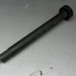
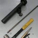
The main body of the tracker was based around the pivot assembly – a modified treadmill roller. Treadmills contain a large amount of useful mechanical and electrical components, so I try to pick up any old treadmills being given away on the local classifieds. After disassembling the roller, I shortened the shaft and body to a practical and aesthetically pleasing length.
The basic idea was to mount the tracker body on a tripod via a quick release plate, attach an adjustable head to the pivot shaft, then drive the pivot shaft with a stepper motor. The pivot shaft needs to rotate roughly 360 degrees per 24 hours, or 1 degree per 240 seconds. More on how that happens below.
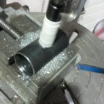
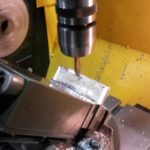
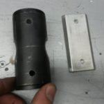
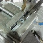
Using hole saw bits on curved metal isn’t a precise process, but I managed to line everything up nicely for the head slot. You will see how it fits into the picture later, but first I need to attach the pivot body onto an Arca-Swiss tripod mount. The adapter plate was manufactured from aluminum (because it’s simply wonderful stuff to machine). The plate then bolts onto the pivot body. I had originally intended on machining a groove into the plate in order to prevent any movement between the plate and body. However, once the plate was fastened onto the body (using two 1/4″ NC 20 bolts), I found the assembly to be very rigid without any further modification.
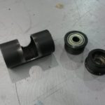
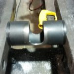
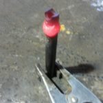
Now, the head attaches to the rotating shaft via a modified tube. A hole with the same diameter as the rotating shaft was drilled radially through the tube, which was then cut at the midpoint of that hole. This allowed it to connect to the shaft at a right angle (see photo). Material was added with a MIG welder and turned down to create a lip for the head to rest on.
Things are coming together. Below is a photo demonstrating the assembly so far. The head is from an old Sony tripod with damaged legs. It’s mounted onto the pivot shaft via the tube described above. A single 1/4NC20 bolt fixes the head and tube to the shaft (you can see it all in the photo). The head is surprisingly well suited for this application.
NOTE: The curved threaded rod described below was removed for Tracker V2.1. The controller and motor are still used in V2.1.
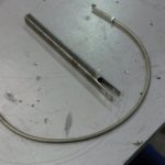
So now we need to drive the pivot shaft. Using what’s known as ‘Farmer Engineering’ (IE. stick your tongue out the side of your mouth and make a decision), I decided to use a piece of #10-32 rod.
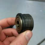
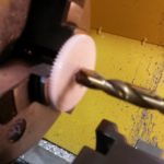
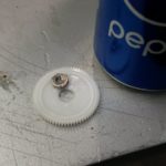
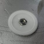
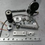
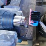
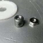
After making the threaded rod roughly circular and building the pivot arm, it was time to add a driven gear and mount on the assembly. The gear was from a bubble jet printer I had just discarded. I easily modified it as shown to accept a nut. Joy turned to sorrow as I discovered that I had modified it to accept the wrong nut (this could have been prevented if I hadn’t made such a messy pile of parts). The correct nut was slightly smaller, but it fit inside the gear well enough to be a temporary solution. The drive gear was also modified to be installed on a stepper motor.
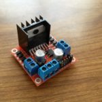
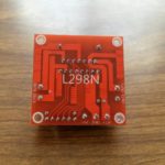
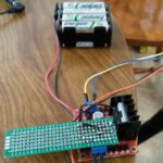
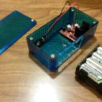
The 28BYJ-48 motor is a dirt cheap stepper with approximately 2047 steps per full revolution. It is described as a unipolar motor, but I wired it as a bipolar motor so that it could be properly driven with an L298N (basically, cut the ground wire and connect opposing coils in series). The power source is 8xAA batteries, which admittedly kicks a bit more power to the motor than I would like. At least I can be confident that the motor will provide sufficient torque and will warm my hands if the nighttime temperature drops (not joking – the motor gets warm!). The L298N was controlled by an ATMEL ATTiny85 microcontroller (affectionately known as a bubblegum chip for its low cost and simplicitiy). The ATTiny was programmed using the Arduino IDE. To give a picture of what’s happening, the ATTiny has four outputs to the L298N. It uses these outputs to command a ‘step’ (really a half-step) every so often (at this point is is set to 1 half-step per 7,957 microseconds). The L298N then provides certain coils inside the stepper motor with 12 volts. Depending on which coils are being powered, the stepper motor will advance to a specific position.
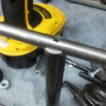
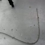
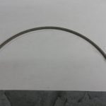
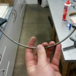
The first issue was that the threaded rod wasn’t a perfect arc. To correct this, I used a compass to draw reference arcs on a piece of paper. Then, by making tiny adjustments by hand, the threaded rod was formed into a perfect arc. I ran a die over the rod to clean up the threads and allow the driven nut to travel easily. Once the threaded rod was properly formed, the pivot arm could travel quite easily.
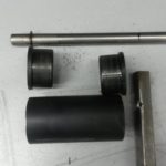
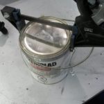
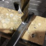
Issue number two was discovered when the speed of the pivot shaft was monitored using a dial guage on the pivot arm. The arm advanced erratically, quickly stepping ahead then stopping repeatedly. The issue was caused by the geometry of the nut and its interaction with the threaded rod. The nut (which rotated at a constant speed) would advance a large distance over a portion of its rotation, then would stop advancing altogether. This was corrected with a custom nut which was longer and essentially consisted of two nuts attached by a ‘spacer’ (the middle portion was not threaded).



0 thoughts on “Tracker V2”