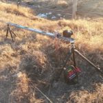
I’ve recently been keen on learning how to use and control stepper motors in a practical application. And it became apparent that the use of a stepper motor in a photographic slider (herein referred to as a PanoSlider) was an excellent challenge to start with. The reason? The PanoSlider had to provide fast, smooth, accurate, and powerful motion while being controlled by an intuitive user interface.
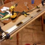
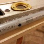
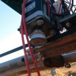
The actual design of the PanoSlider began in a typical fashion: by wandering around my collection of materials and devising a simple, easy, solid structure. I settled on a discarded construction level as a frame. 3/4″ PVC pipes were screwed onto the sides with sheet metal screws, and hot-melt glue (HMG) was added to prevent the pipes from rotating. HMG is a generally underrated material, and its use is often limited to children’s crafts (and results in many finger burns). In reality, it can be used as a fast-setting substrate with good strength, and its poor bond strength is useful in making temporary joints (for instance – I mounted the Arduino board to the PanoSlider assembly with HMG, then simply broke it off when it was no longer needed).
The challenge in this case was building a code for the Arduino which could perform two tasks: still-shot timelapses and video pans. For the still-shots, I utilized a library called AccelStepper. The library provided the exact functionality I needed – after setting a maximum speed and acceleration rate, you simply command it to move to a new position. The Arduino would then idle until it was time to take a shot, then it would actuate the camera shutter for the set time. The downside to the AccelStepper library was that it could only create a linear acceleration, which demanded far too many calculations from the Arduino when moving at high speed. Result: a max speed of 3.5 inch/second, too slow for video pan shots. So for the video mode, I came up with a pseudo-linear acceleration, which was far simpler for the processor to calculate each step. Instead of calculating an inverse-square between steps, the processor was only required to do addition. The maximum speed at which I could consistently operate the motor was at 15khz = 13 inch/second on the slider (2mm belt tooth pitch; 36 tooth sprocket; 200 full steps/motor rev; 1/16 steps).
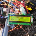
The menu is displayed on a 16×02 LCD display and controlled by a single encoder switch. Ideally the entire package should be contained on a shield which can mount on an Arduino board and should be protected with a weatherproof case. I’m not going that far with this project, as it will only be used occasionally. There are a few issues with the encoder, which creates electrical noise and consequently jumbles the communications to the LCD display. This can likely be handled with better debouncing.
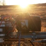
The great majority of the power is drawn by the motor. Current is controlled by a potentiometer on the motor driver. On a level surface, 150mA is suffecient to move the carriage with any dSLR (measuring at the power supply – motor current will be greater). When travelling up a gentle incline, the current can be increased to at least 300mA and the motor becomes very torquey. At either of these power rates, a pack of 8x AA batteries would be sufficient for several hours of run time.
Enjoy!