PREAMBLE:
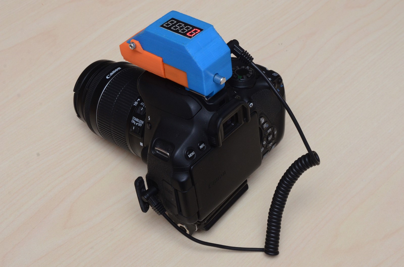
A friend and I set out to build a camera intervalometer for DSLR cameras. Instead of following one of the many build guides available online, we decided to design our own – The Mikro-Chronograph. Check out the feature list:
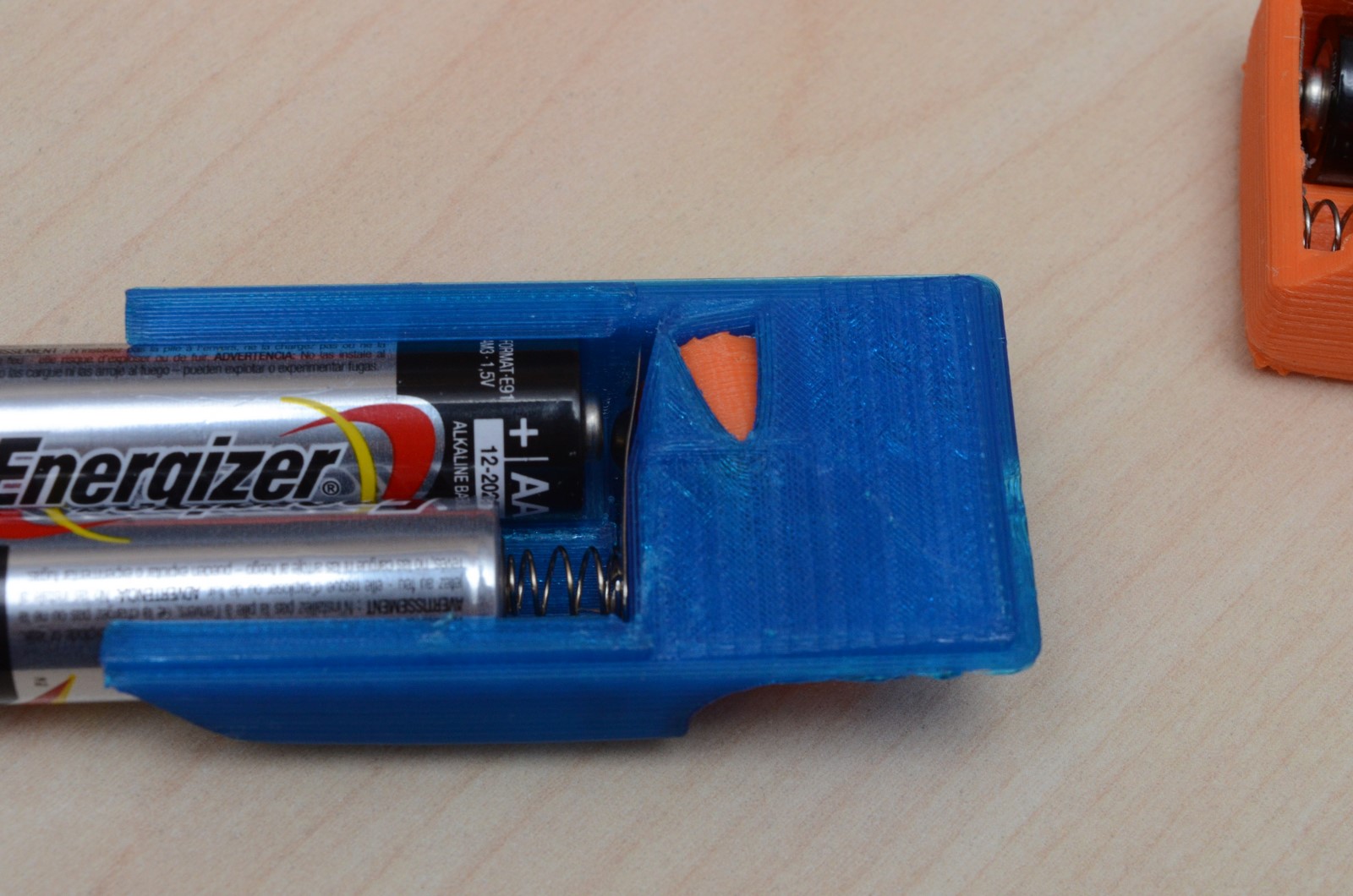
- 2x AA batteries with a ridiculously long battery life
- LED display functions in any temperature (eg. Canadian winter) and has fancy features such as scrolling text and swirling icon
- Tiny!
- Encoder/button combo input is very simple and intuitive
- Very fast to setup: Initial Delay, Shutter On Time, Shot-Shot Delay, and Number of Shots
- Automatically load the last settings each time the intervalometer is turned on (with EEPROM wear levelling algorithm, it will easily outlast a professional camera)
- Can be extensively customized without reprogramming, including screen orientation & brightness, input styles, clock speed calibration, and memory behaviour
- Safe to use with any DSLR, thanks to the optoisolator
- Price Tag: less than $20 CAD
If you want to build one, just get the components listed, wire them up on a PCB board (look at the photos below for a layout guide), program the ATTiny85 with the available code, and build a case. All of the details can be found on Google Drive. The 3D printed case designs are on Thingiverse.
Also, you will need to program the ATTiny85 microcontroller. Here is a great guide for doing this using an Arduino!

COMPONENTS:
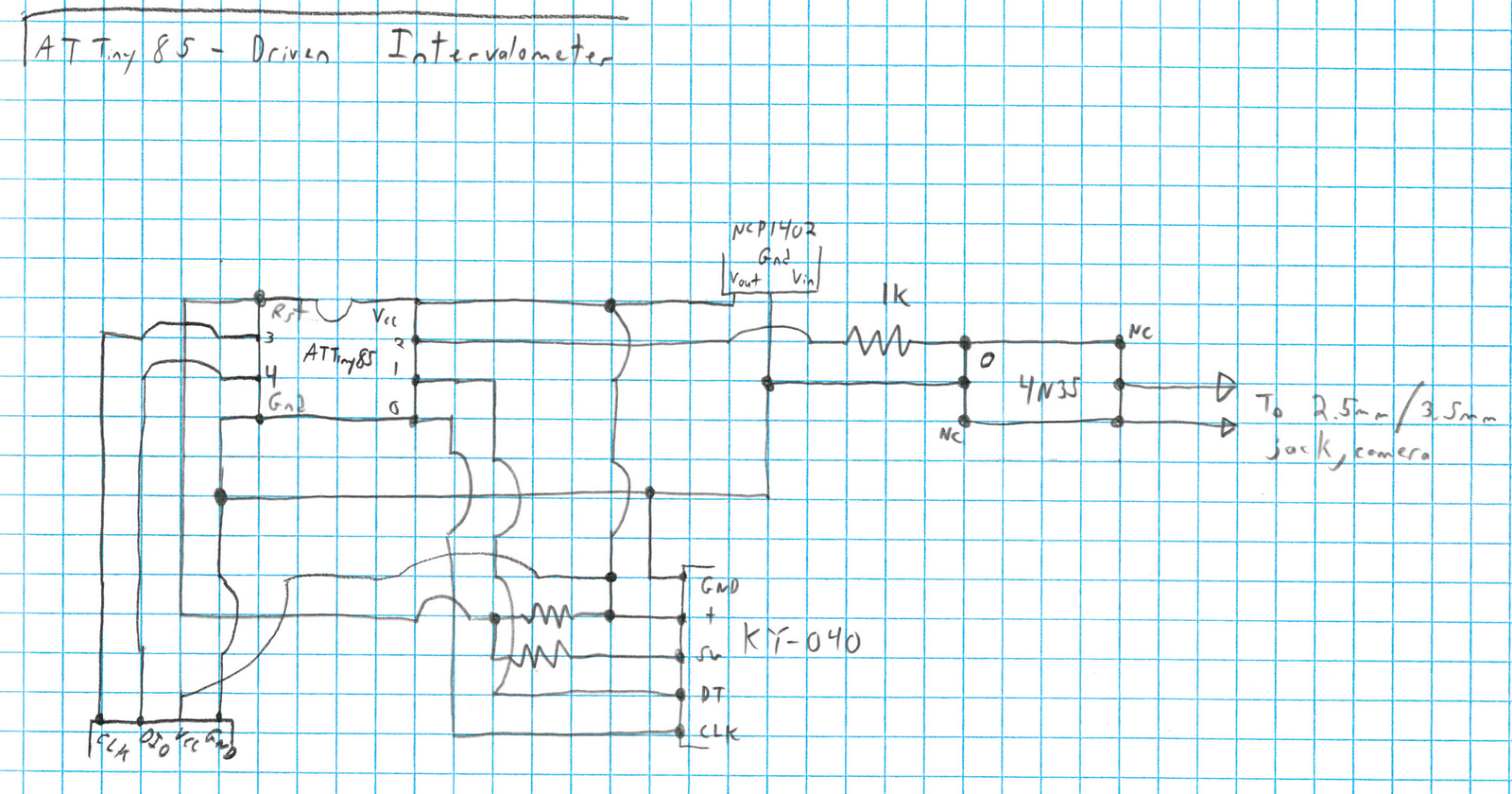
The Mikro-Chronograph uses an ATTiny85 microcontroller. They are VERY cheap ($1.50 CAD) and have only six GPIO pins. This is the perfect size to take inputs from an encoder (3 pins), display data on a 7-segment LED display (2 pins), and control a camera (1 pin). It’s important to note that one of the ATTiny’s pins will reset the microcontroller if driven low, but can read analog voltages so long as it stays above about 3 volts. This is important for the next bit. While the reset function can be disabled with a high-voltage programmer, it adds lots of frustration with code development and re-programming the chip. It’s easier to leave the reset function intact and design around that problem.
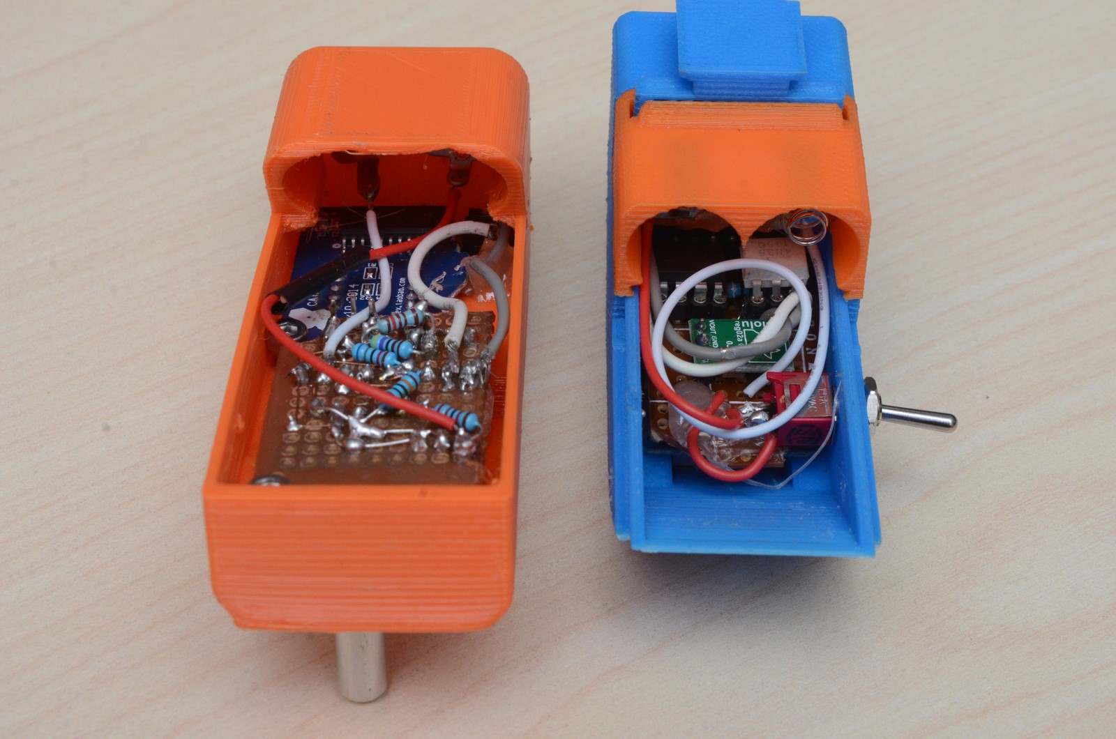
The display is a four-digit 7-segment display driven by a TM1637 controller ($1.50 CAD from eBay). The input device is a KY-040 encoder ($1.00 CAD from eBay). It provides a quadrature output for the rotary encoder and a pullup output for the button. The button output goes through a voltage divider, which outputs 5 volts at rest and 4 volts when the button is depressed. The button can then be connected to the ATTiny’s reset button and an analog voltage can be read.
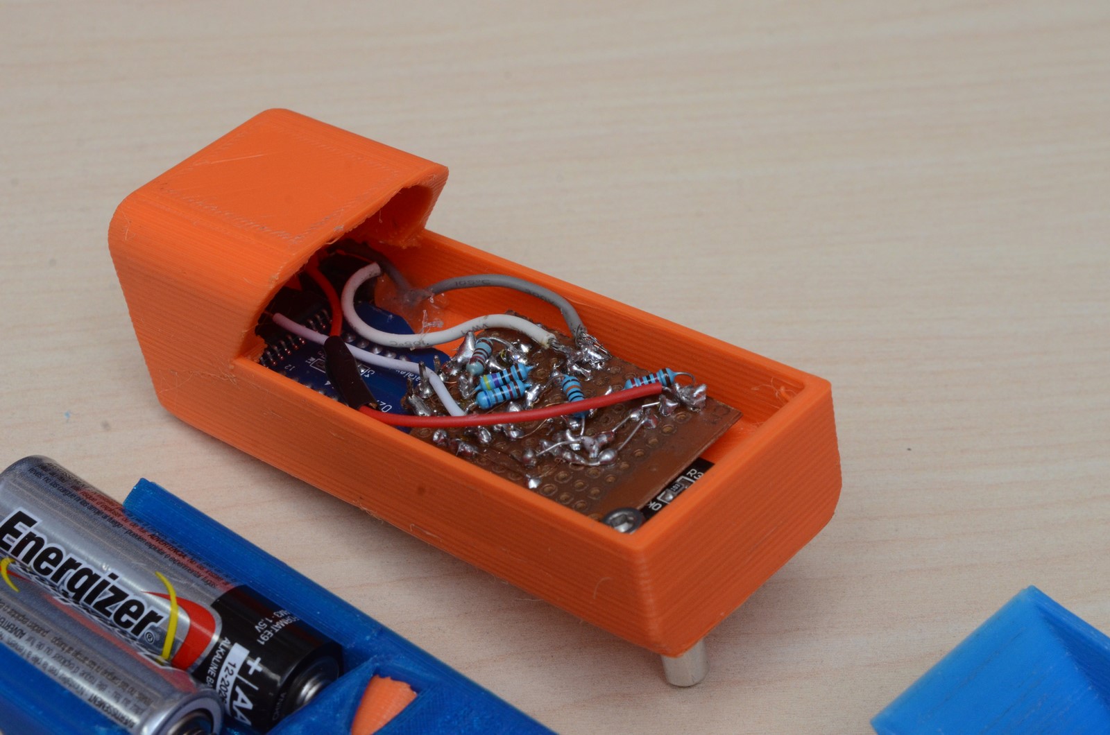
The last free pin on the ATTiny is connected to a 4N35 optoisolator by a 1K Ohm resistor. This protects the camera from any damage, as there is no electrical connections between the power supply and the camera. My Canon 5D classic would not actuate when higher resistance than 1K was used, but a 7D mk1 and a 700D responded to the higher resistance.
NOTE: It recently occurred to me that a camera may be safely actuated by grounding the camera directly to the microcontroller, and toggling a GPIO pin (directly connected to the camera) between a low-voltage state (OUTPUT LOW) and a high-impedance state (INPUT). The controller would never provide voltage to the camera.
The recommended voltage limits for the ATTiny was 2.7 – 5.5 Volts To protect the ATTiny and prolong battery life, a Polulu NCP1402 ($7.50 CAD from Solarbotics) takes power from two AA batteries and outputs 5V.
USER INTERFACE:
Having a 4-digit, 7-segment display presents an interesting set of challenges regarding the user interface. Many letters don’t really translate into 7 segments well, so some thought was put into the text displayed by the intervalometer. Additionally, the display can scroll text, allowing strings longer than 4 characters to be displayed elegantly.
The Mikro-Chronograph has four basic settings, ‘session settings’: the initial delay (time before first actuation), bulb time (length of actuation), actuation – actuation time (time from end of one actuation to beginning of next), and number of actuations. The session settings are saved to EEPROM memory and, depending on the user settings (see below), are automatically loaded on startup.
In addition to the session settings, a series of user settings are stored in EEPROM memory, so that the Mikro-Chronograph always behaves the same way each time it is turned on. The user settings include screen brightness, screen orientation, encoder direction, control scheme (more on this below), clock speed calibration, session memory settings (RECALL and ZERO), and an EEPROM reset. The user settings menu can be accessed anytime by long-holding the button and the settings are automatically saved when the menu has cycled through all of the user settings and returns to the session settings. Following are a list and descriptions of the user settings:
- BRIGHTNESS: rotate the encoder to adjust the screen brightness. This is not saved in EEPROM and defaults to full brightness on startup.
- SCREEN ORIENTATION
- ENCODER DIRECTION: changes encoder polarity, change if you want to reverse the encoder’s direction
- SIMON / TYLER INPUT STYLE: See Below
- CLOCK CALIBRATION: 1000 is default. If timer is running slow, increase number. If fast, decrease number.
- CAMERA TEST: Turn encoder right to toggle camera pin open / closed. Turn encoder left to take a single photo.
- SESSION MEMORY SETTING: RECALL – the intervalometer will load the previous session settings on startup. However, if the button is held on startup, then the previous session settings will not be loaded. ZERO – the intervalometer will not load the previous session settings UNLESS the button is held on startup.
- RESET: Turn encoder to clear EEPROM memory (recommended to do once after microcontroller has been programmed).

Two control schemes were developed and are named after the developers: Tyler & Simon. The ‘Tyler’ scheme, or T-scheme, is faster to adjust but only allows certain values for each setting. Turning the encoder cycles through the available values, which look something like this: 1, 2, 5, 10, 15, 20, 25, 30, 40, 50… up to 9999. Depressing the button cycles to the next setting and the actuations are started in the ‘GO’ screen by turning the encoder two clicks in either direction.
NOTE: While 9999 is the maximum value allowed due to the 4-digit display, it’s actually a huge value for an intervalometer setting. 9999 seconds is almost 3 hours. But what if the user wants a photo every 6 hours? Just take a photo every 2 hours and delete the intermediate photos.
The ‘Simon’ scheme, or S-scheme, allows any value for any setting between 0 (or 1, depending on the setting) to 9999. Rotating the encoder cycles through the settings. Pressing the button will cycle through each digit of the setting, at which point rotating the encoder adjusts that digit. This takes more time, but allows more precision for each setting.
When the intervalometer is running a session, the user can control the display by turning the encoder and pressing the button. By default, a swirl icon will appear when a photo is being taken. A short click of the button will toggle the swirl icon off and on. A long hold of the button will cancel the session and return to the session settings menu. Turning the encoder right will cycle through:
- Photos Left
- Time Until Next Photo
- Total Time Left
Turning left will cycle between:
- Continually cycling screen showing all of the above information
- Turning the screen off (improved power consumption)
CODE:
The firmware is available on GitHub.
The behaviour of the intervalometer can be adjusted in several ways. Several settings can be adjusted in the definitions at the top of the .ino file. The selectable values for the T-scheme can be found in an array. The text strings can be modified in the strings.h file, but the length of the strings must also be set in the current version of the code.
While there are libraries for handling encoder inputs to the controller, it was more fun to write the code from scratch. The encoder outputs are polled regularly so to prevent any lag or errors. Sometimes the encoder can be turned faster than the microcontroller can detect. The controller will try to detect when this happens, and will go into a high-speed rotation mode where it assumes that the encoder is not changing direction and will perform multiple steps at once. This results in a typically lag- and error-free use.
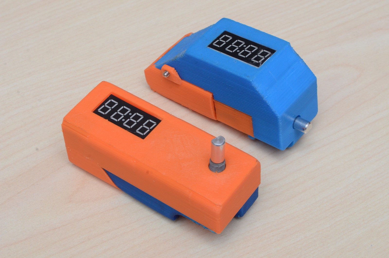
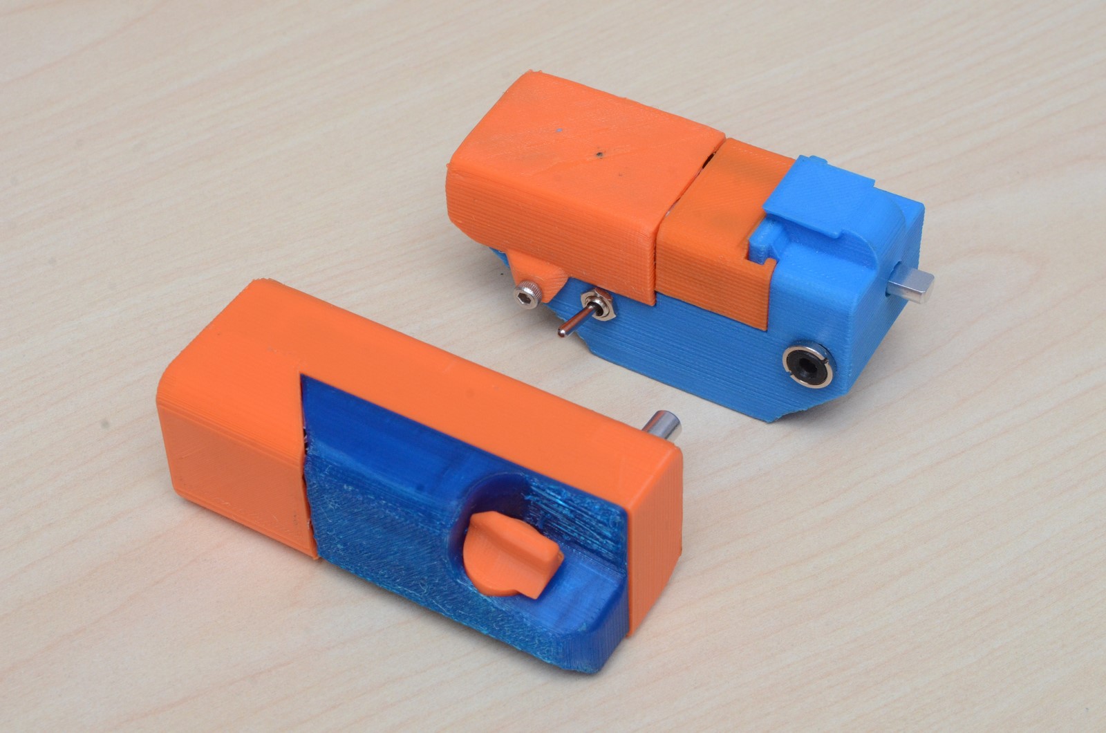
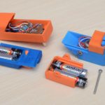
FINAL PRODUCT:
I am hesitantly sharing the cases we designed for the Mikro-Chronograph since they were built to barely accomodate the component layout we came up with. If anybody else builds one, the layout may be different and the cases may not work. If you are inclined to replicate our models, feel free to use the case designs on Thingiverse! If you 3D print a case, make sure and use PETG (or ABS) as PLA has a habit of deforming in direct sunlight. The springs for your AA batteries will definitely push the case apart in summer heat.

FUTURE IMPROVEMENTS:
- Eliminate the optoisolator
- Battery level monitor with voltage display, warning, and automatic shut-down
- Various code improvements allowing easier text string modification
- User setting for the default session operating information display (currently displays the cycling display by default)
- Custom function for operating a camera with the mirror lockup enabled
Thanks for reading!
There are a few cameras (specifically, my X-Pro1) out there without electronic cable releases or built in intervalometers. Is there enough code space to add PWM output from the ATTiny to drive a servo that actuates a mechanical release? The Polulu step up regulator should be able to power a small servo.
That is a really good idea. I hadn’t thought about driving a servo, but it could definitely be implemented.
What I would suggest is to have an option hard-coded in the firmware for built-in release VS servo release. That’s because I am fearful of applying 5V to a built-in release, which is pulled up to about 3V. I don’t know but 5V may damage the camera.
I just realized that the firmware isn’t available online, let me put it on GitHub. It shouldn’t be hard to change the output, just change the Pinmode to Ouptut, and ShutterOpen and ShutterClosed functions to a PWM output.
I see from your Thingiverse profile that you’re in Calgary as well. I’m in Triwood (Northmount Dr. and 19th NW). I was thinking a second module that is driven off the output of your release would work well. If it just clamped around the top of a cable release and had its own power it wouldn’t clutter up the top of the camera.
You live hilariously close to my office (in Hungtington). I live out of town (Linden) but am in the office every weekday.
I’ve been waiting for a good excuse to try mill a PCB board. Do you want a board? If you have a method of programming an ATTiny85 (I recommend this: https://solarbotics.com/product/50845/) then you could take the board and play with the firmware yourself. If no then we could work together to update the firmware. A 9g servo would probably work perfect for actuating the shutter!
I’ll definitely take a board, that would be great. I’ve got a USBTinyISP that will program the ATTiny, and a programming jig with a DIP8 socket. I’ve got some 9g servos and a few nano sized ones as well. What do you think about a servo based linear actuator (https://www.thingiverse.com/thing:2803149)?
I’ll try get to that this weekend. About that linear actuator, I’m hesitant about the 3D-printed rack and pinion. It introduces complexity and friction. If the servo has a lever to press the shutter, that would be simple and robust. Just my two cents!
Could you email me a photo of your programming jig? tyler@td0g.ca. I’ve wanted one for a while now.
Edit: I just looked at the X-Pro1. It has a threaded shutter button. I think it should be easy to use a servo to actuate it…