
PREAMBLE:
Note: As of August 26, 2019, the most incredible home-built camera rig award goes tomingul’s 8-Degree-Of-Freedom robot! It takes up an entire room and can be given gcode to perform some amazing camera effects. My rig isn’t as cool, but much more mobile and simpler to build.
Camera sliders are fun tools to use for making dynamic timelapse videos, and they come with some cool features. This is a clever little gadget that moves like a camera slider but folds much smaller. Eggtimers are also commonly used to make a similar effect. Some high-end gear can slide and rotate the camera at the same time for a particularly cool effect. But how do you guild one that one that could go up to 11?

IREnE (Inverted Radial, Extension, Eggtimer) is not only named for the clever woman (nee Adler) who outsmarted Sherlock Holmes , but also the clever functions it can perform. The ‘Inverted Radial’ is the slider’s defining feature which doesn’t seem to be possible on any consumer camera sliders. It moves the camera in a circle around the foreground subject in a way that keeps the subject in view while the background view is constantly changing. Here are some examples:
BASIC CONCEPT:
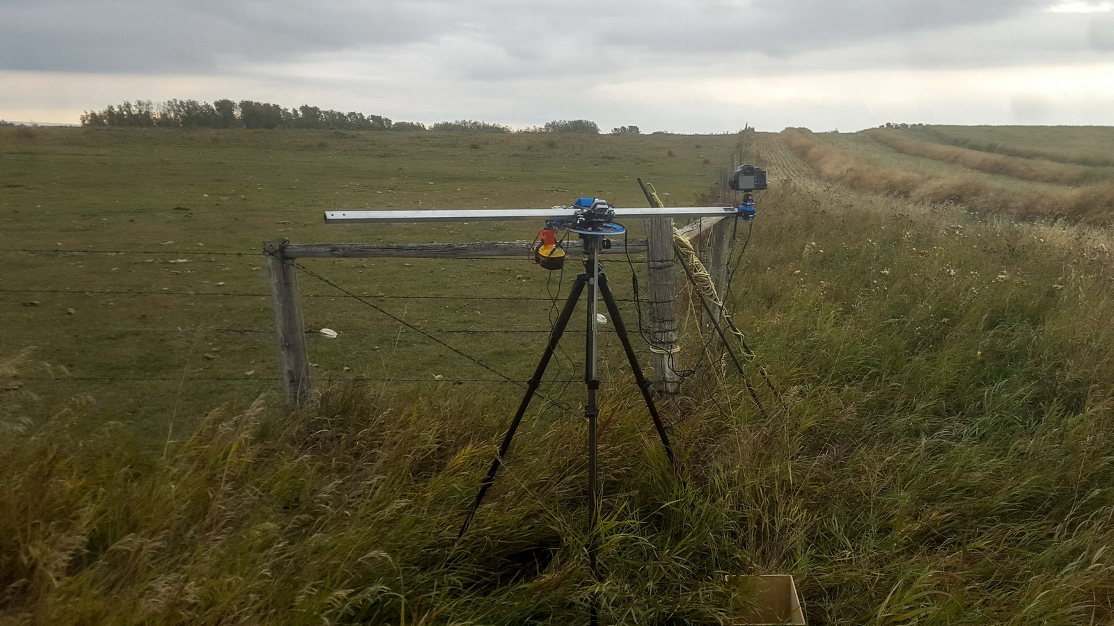
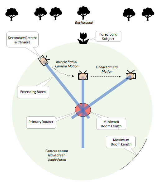
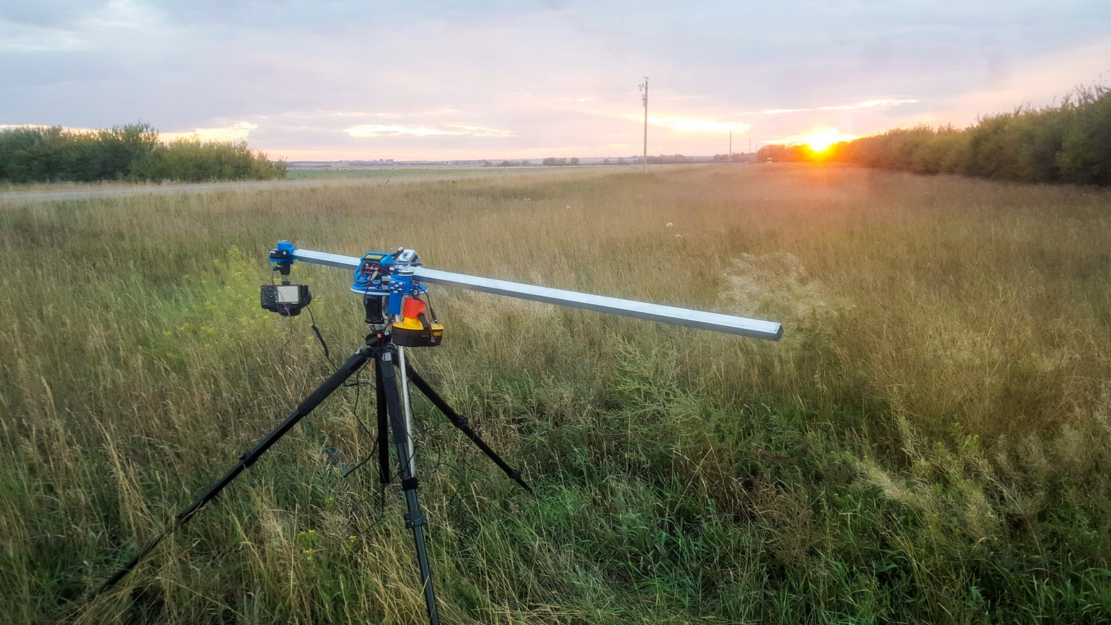
The slider has three degrees of freedom: A primary rotator mounted right on top of the tripod, an extending boom, and a secondary rotator at the end of the arm. This setup allows the camera to move anywhere inside a circle where the radius is the maximum extension length of the boom – except it cannot move inside a smaller circle where the radius is the minimum extension length of the boom.
The particular boom I used has a max length of 150 cm and a min length of 25 cm. The longest straight movement possible with that arm is 246 cm. That means a machine only 150 cm long can replace a traditional slider 246 cm long! Keep in mind that extending to 150 cm requires a good tripod and head – and no wind.
The rig also happens to be perfect for some other applications. I built and installed a pancake batter extruder and printed some fun pancakes. That modification was documented in another post.
CONSTRUCTION:
Here are a ~few~ photos. Note that there have been minor changes and upgrades along the way, so some photos may show parts which were later replaced.
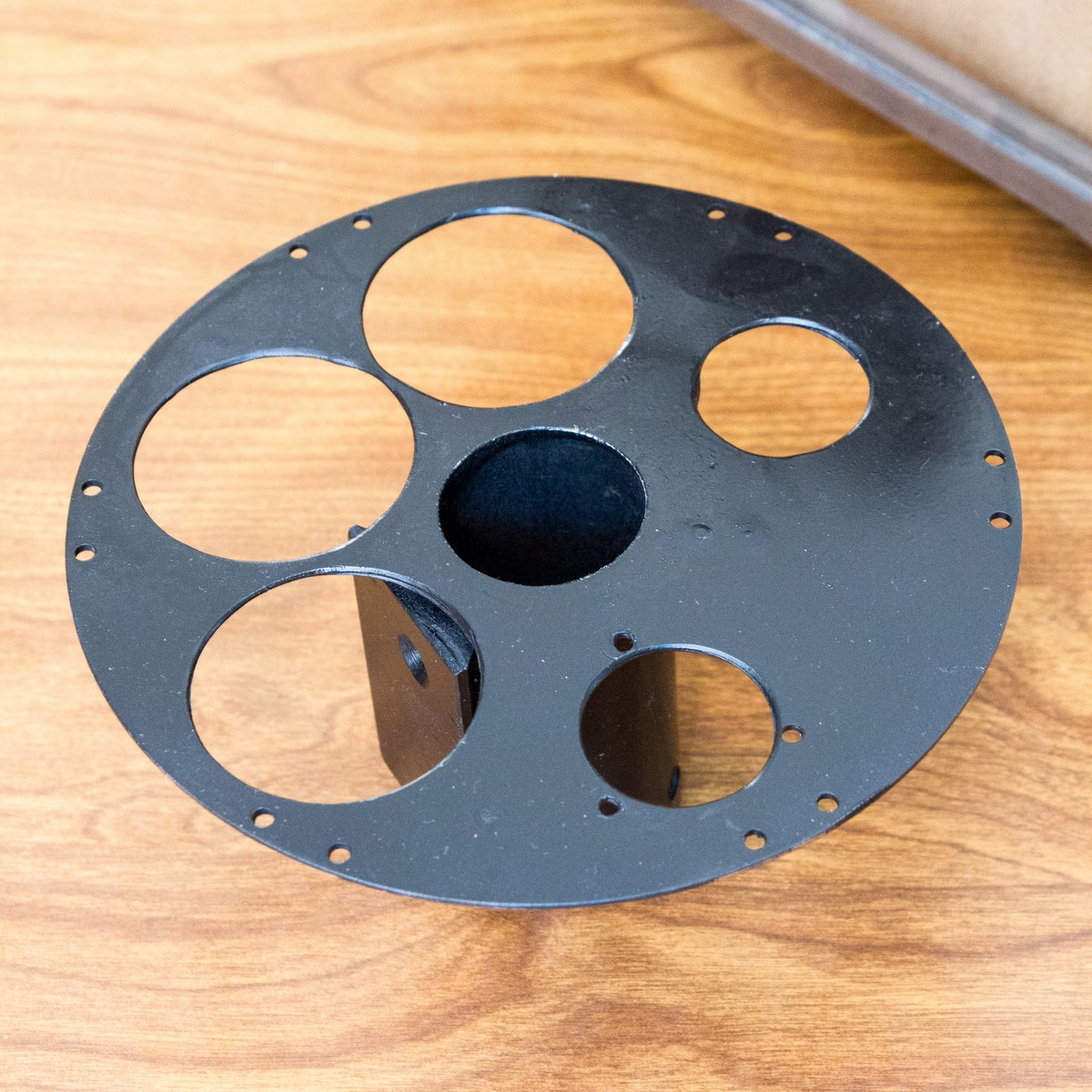
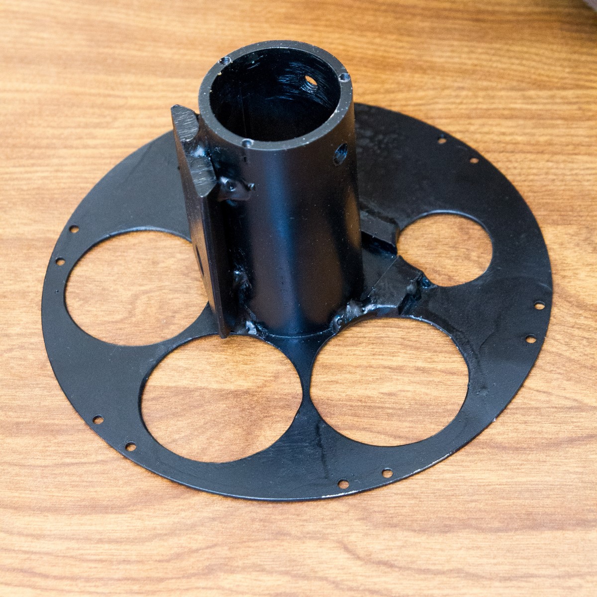
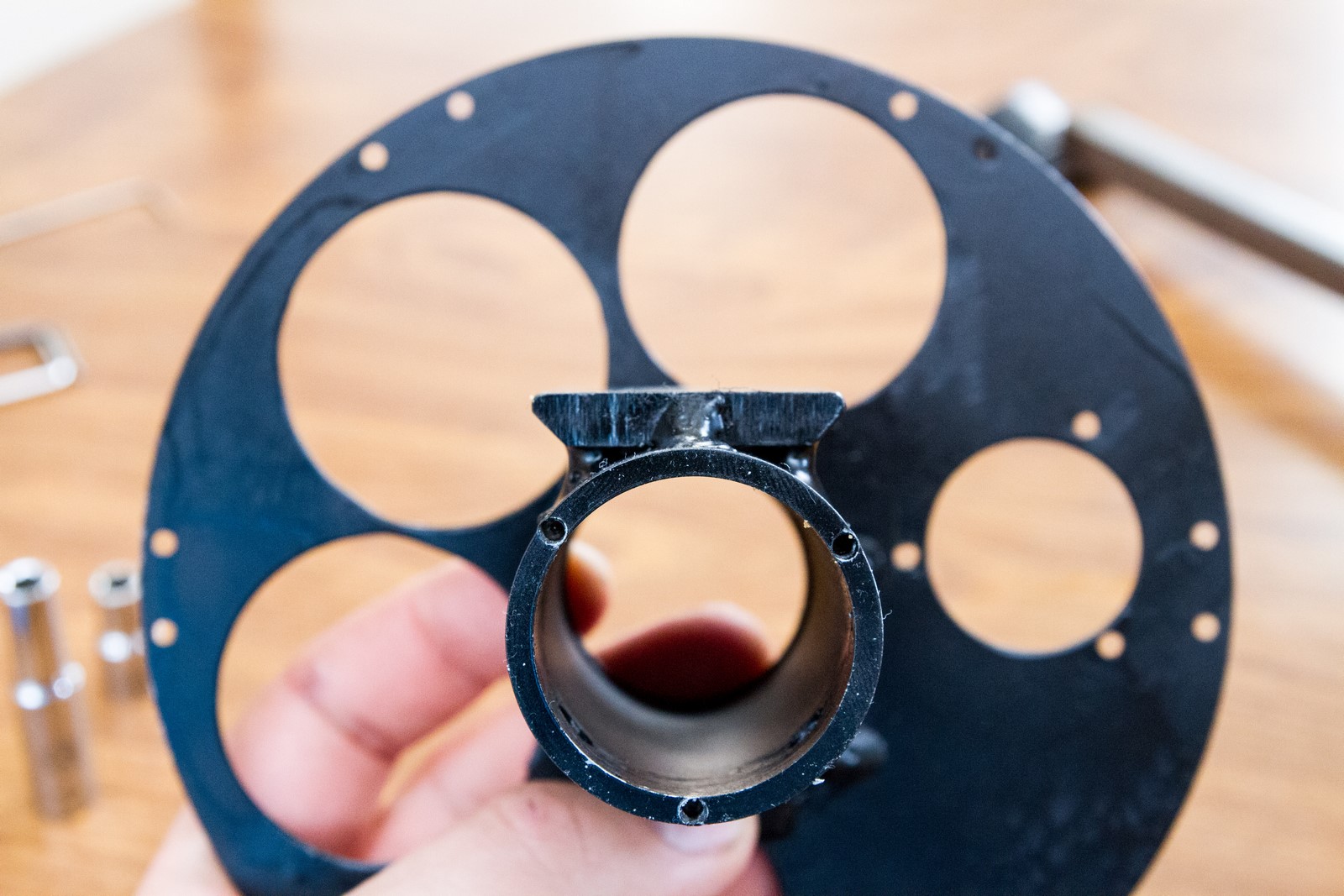
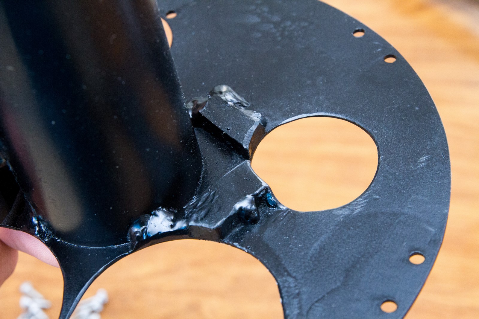
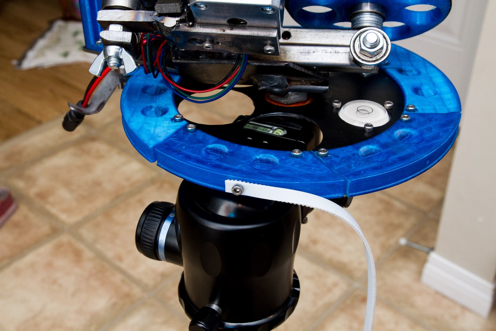
The base has a tube to mount the bearings, a top plate to hold the primary rotation pulley, an Arca-Swiss compatible mounting block, and a wedge mount for the stabilizer bar (see below for more details on that). The holes in the top plate are partially functional and mostly aesthetic.
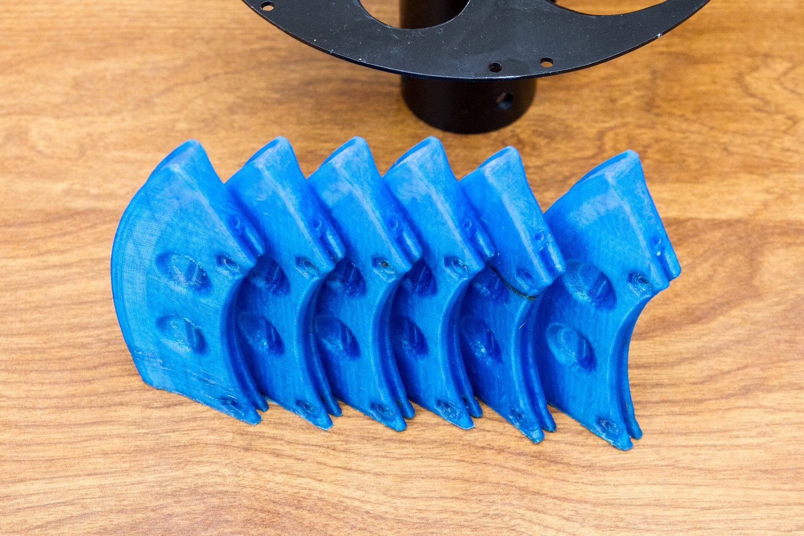
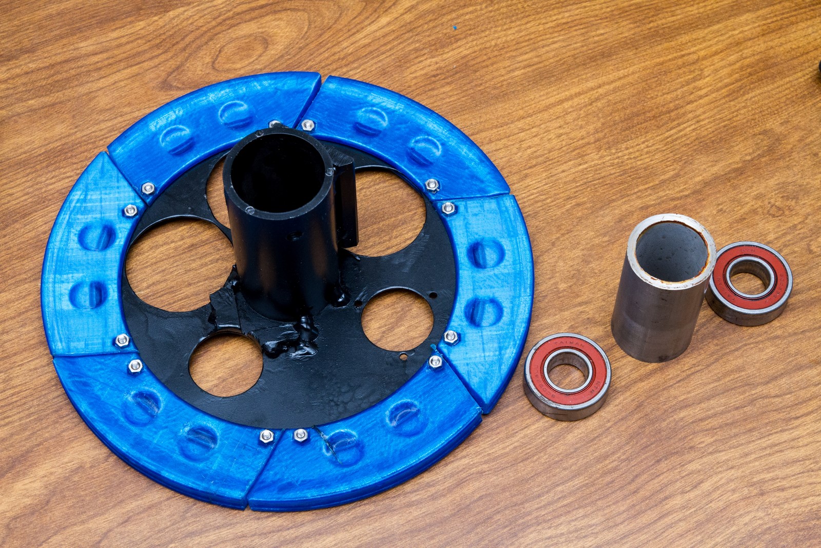
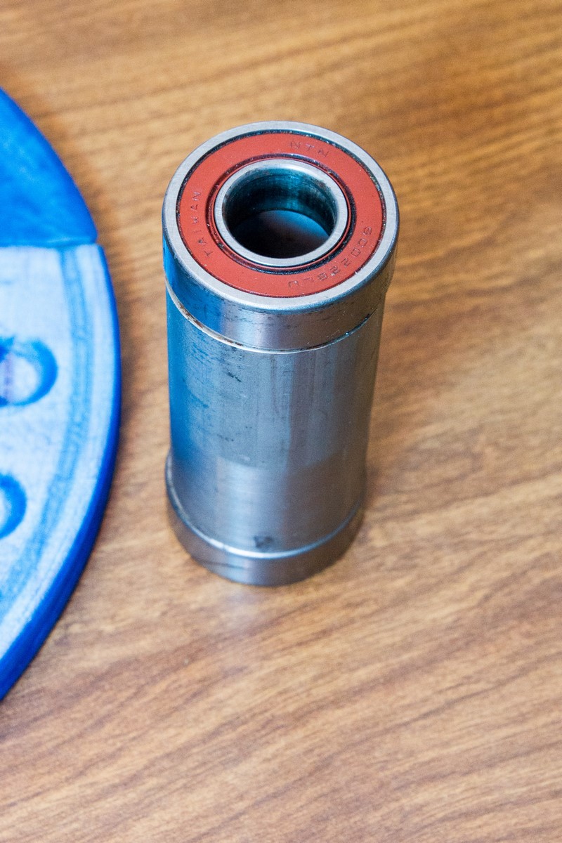
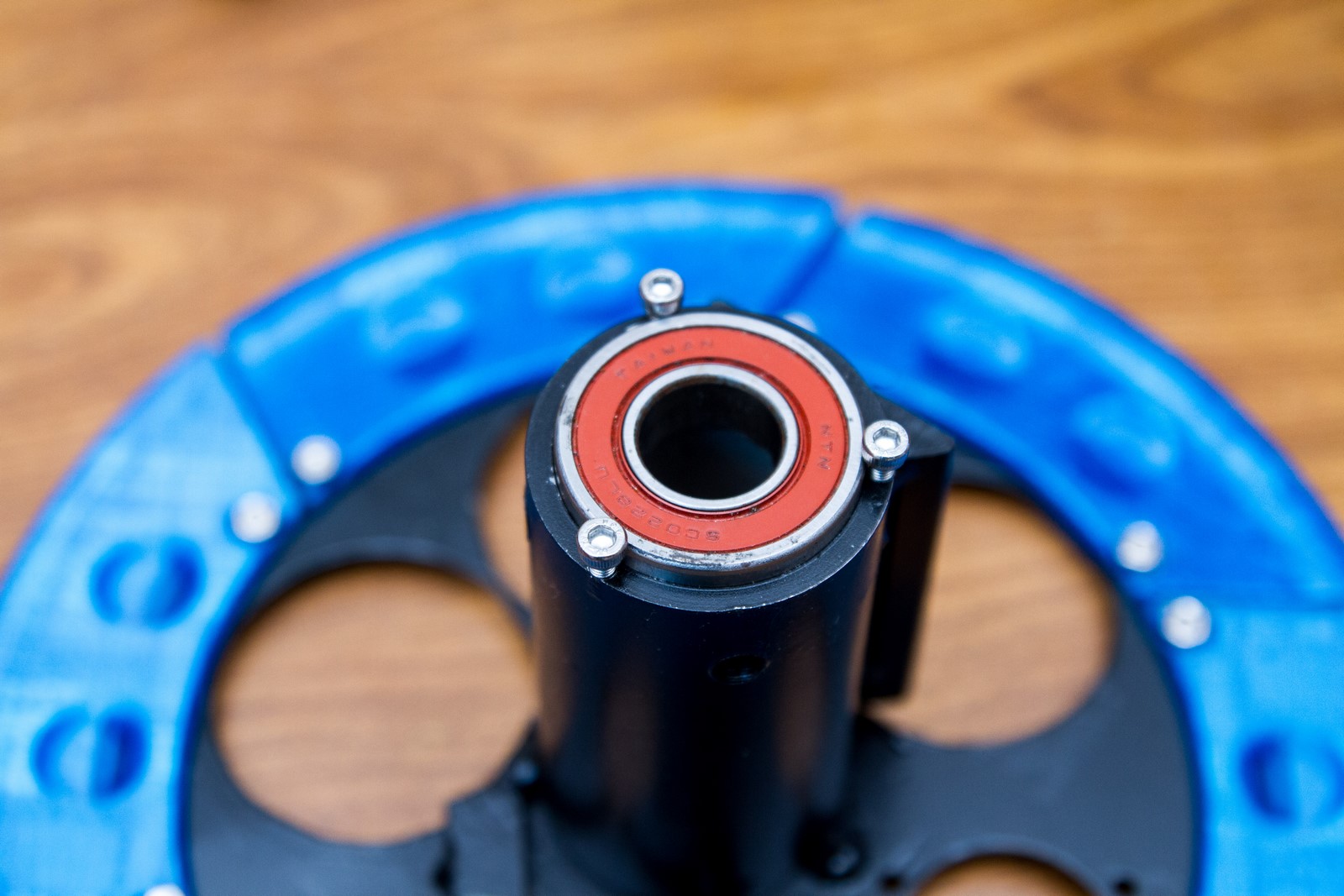
I 3D printed the primary rotator pulley in six sections. They are shaped like little AK-47 magazines… This was done to make them easier to print, since they are fairly vertical. All 3D printed parts are made from PETG to withstand the outdoor environment. The two bearings were installed in the tube with a spacer between.

I had some help putting everything together.
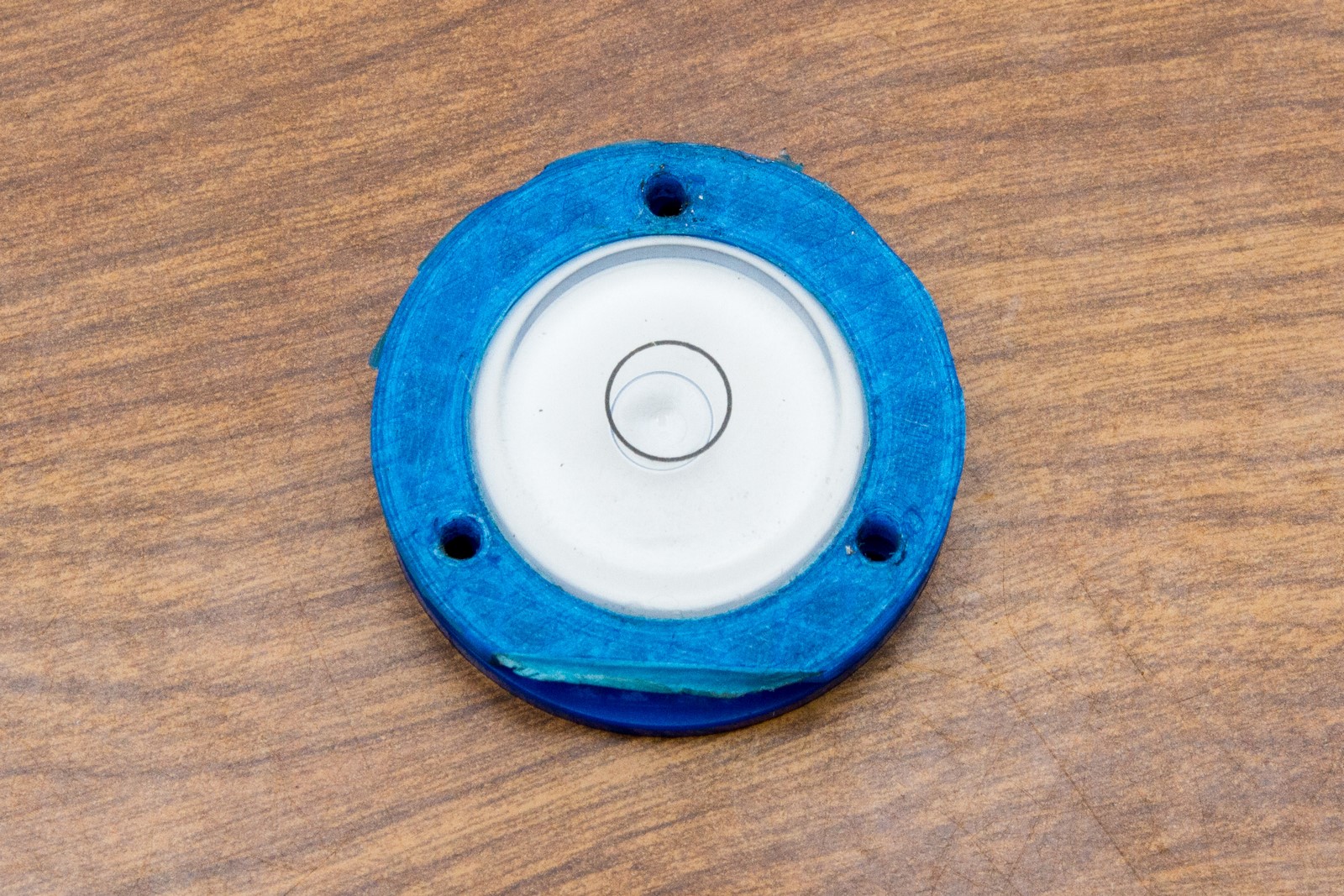
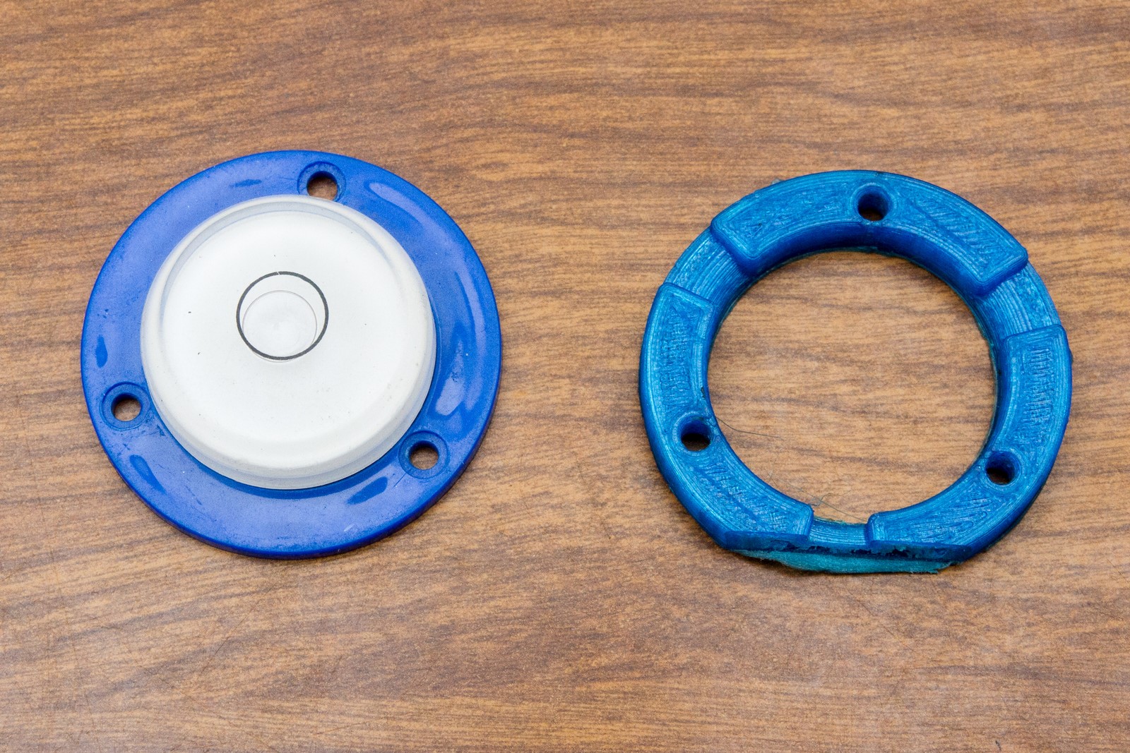
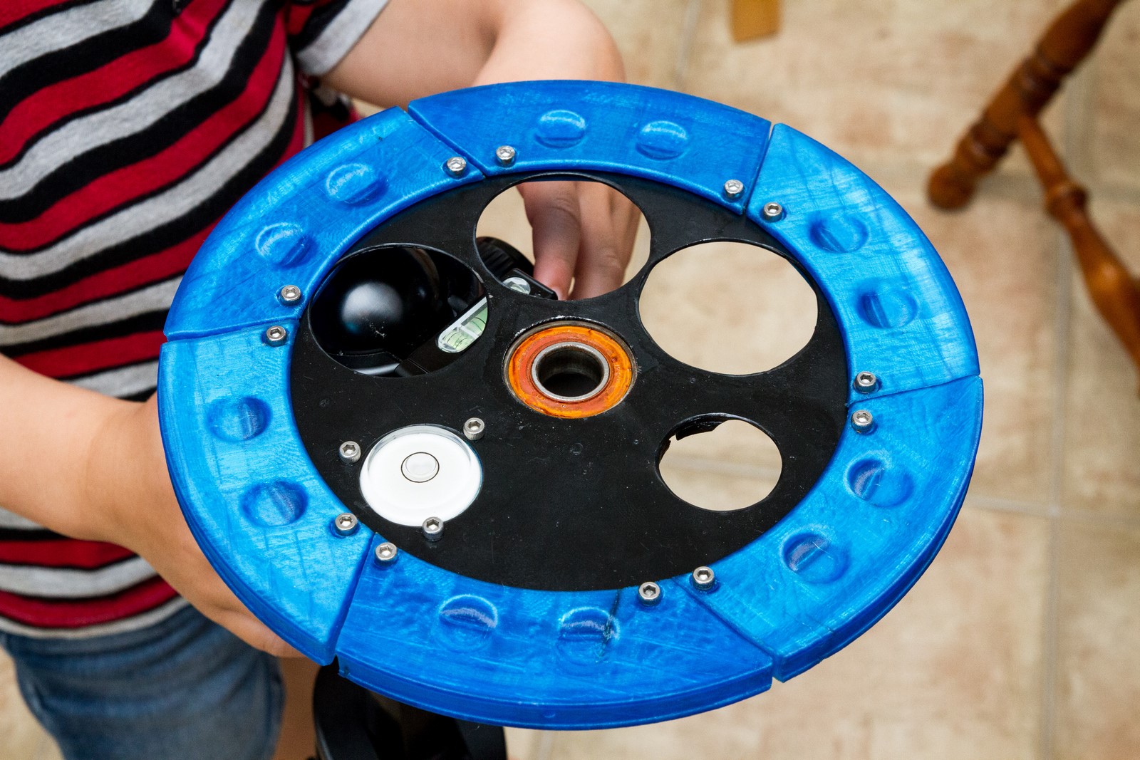
A bubble level mounted on the base helps for levelling in the field.
The rotator slides right through the bearings and is fastened by a nut on the bottom.
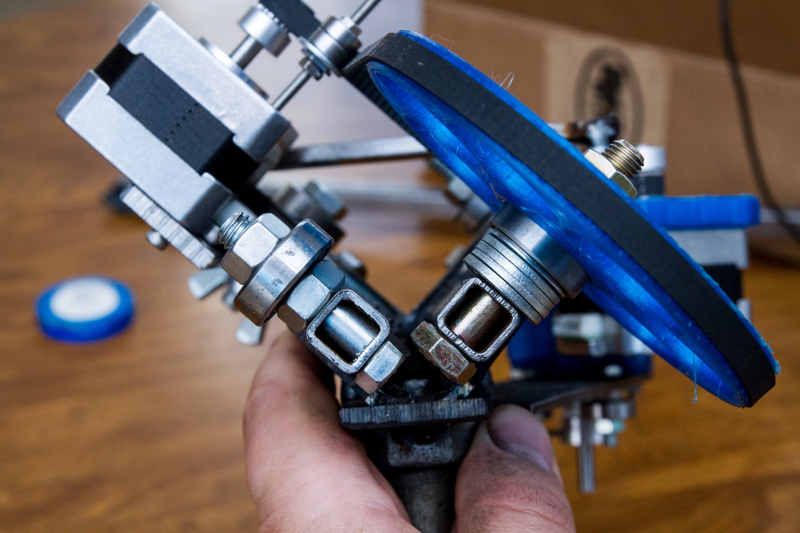
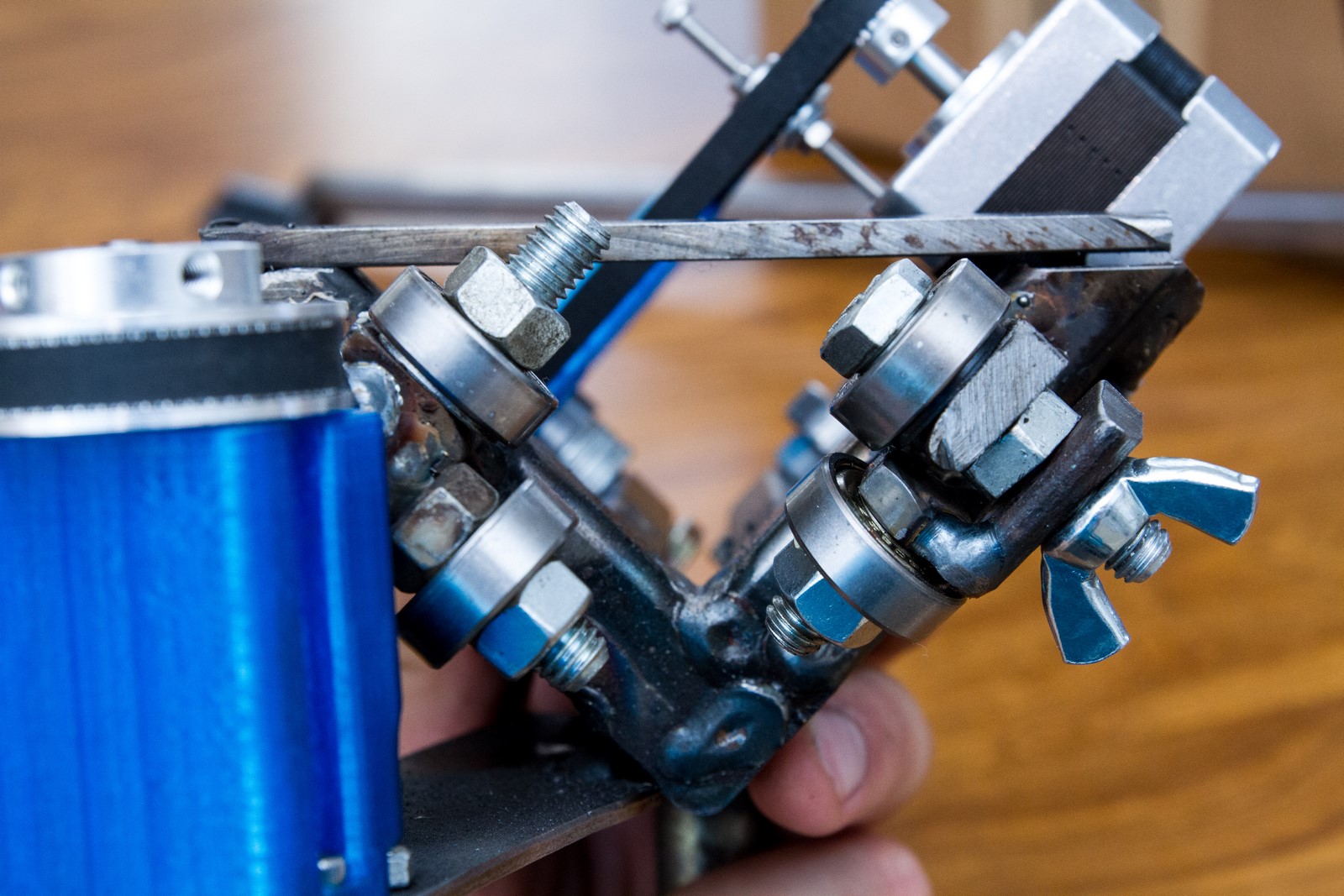
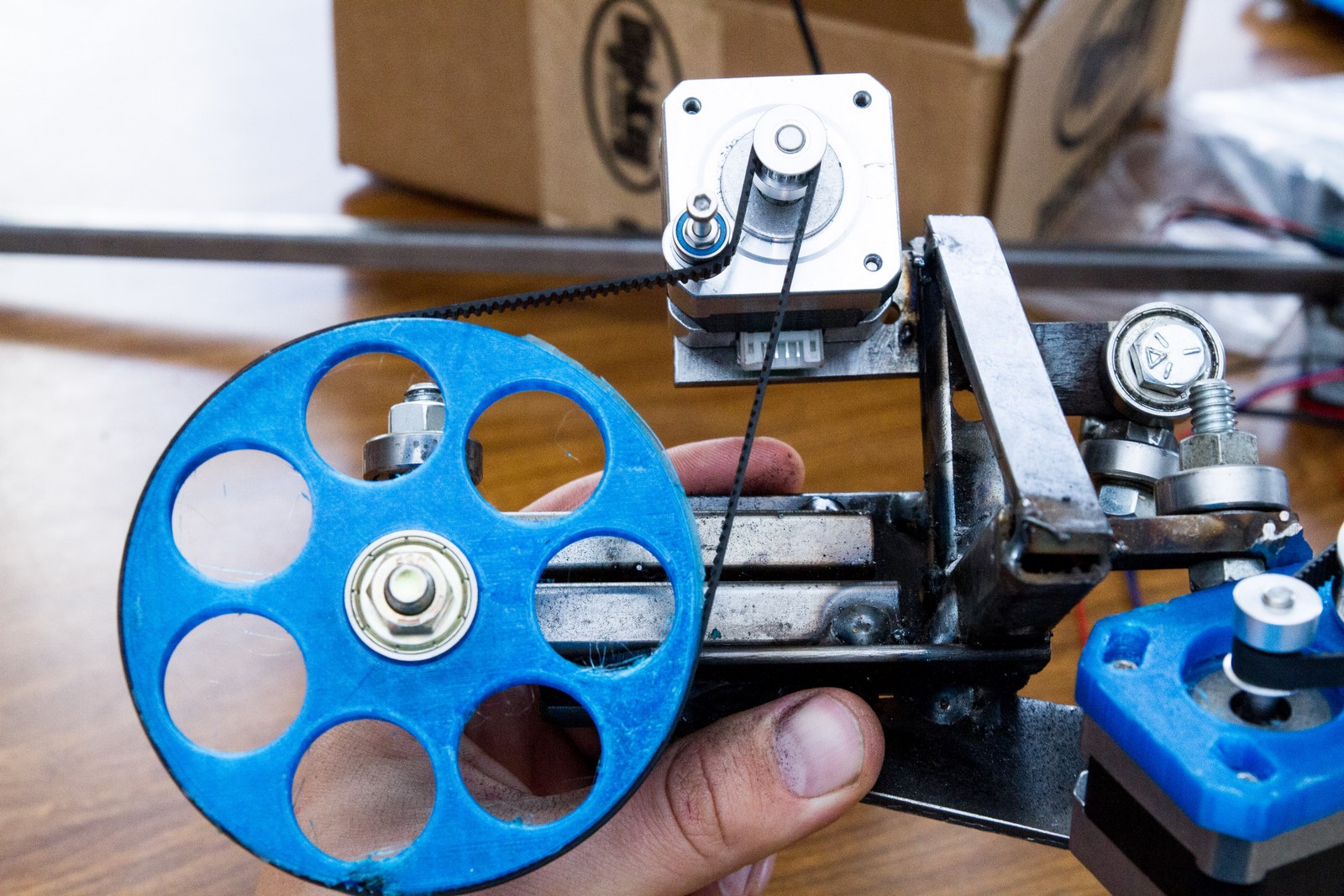
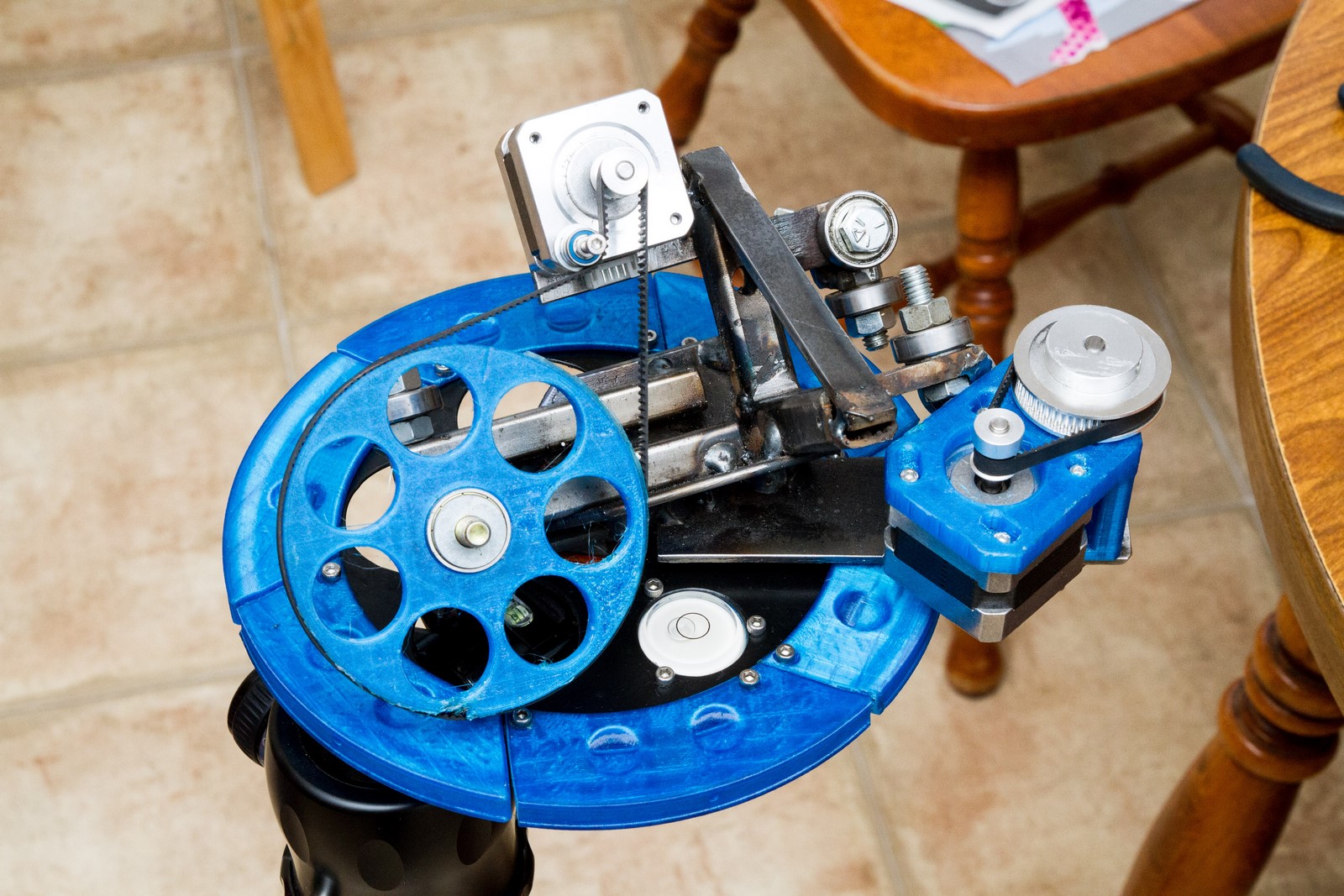
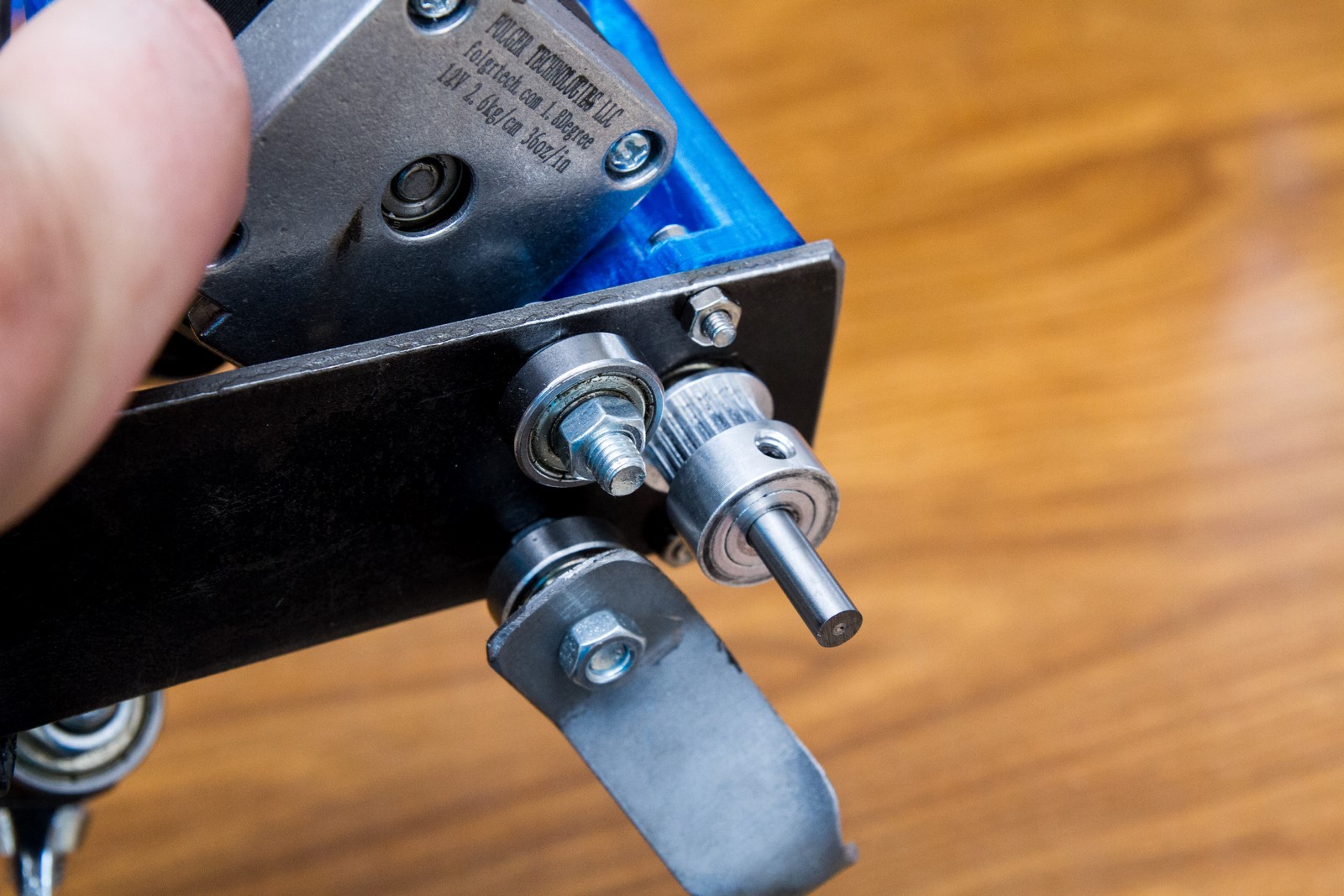
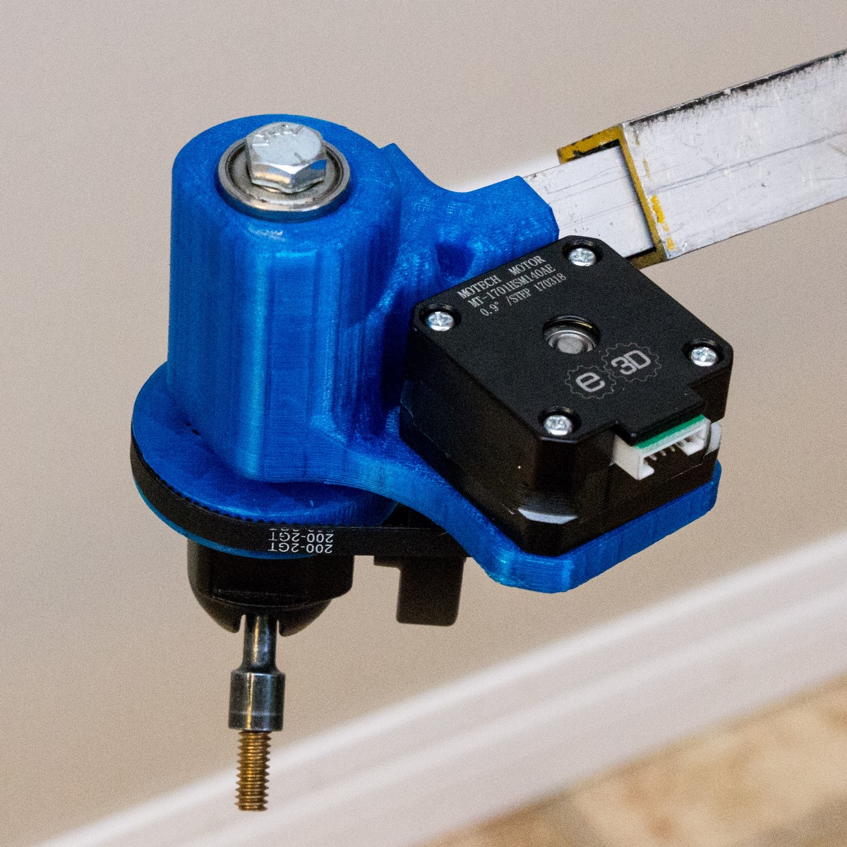
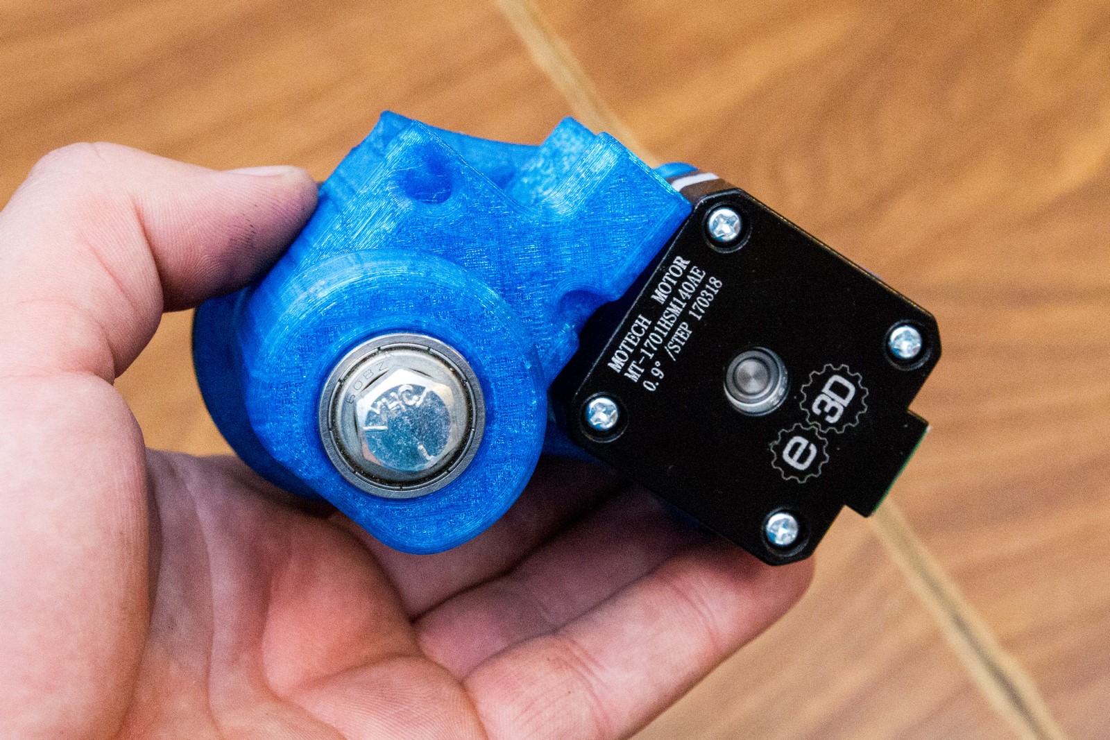
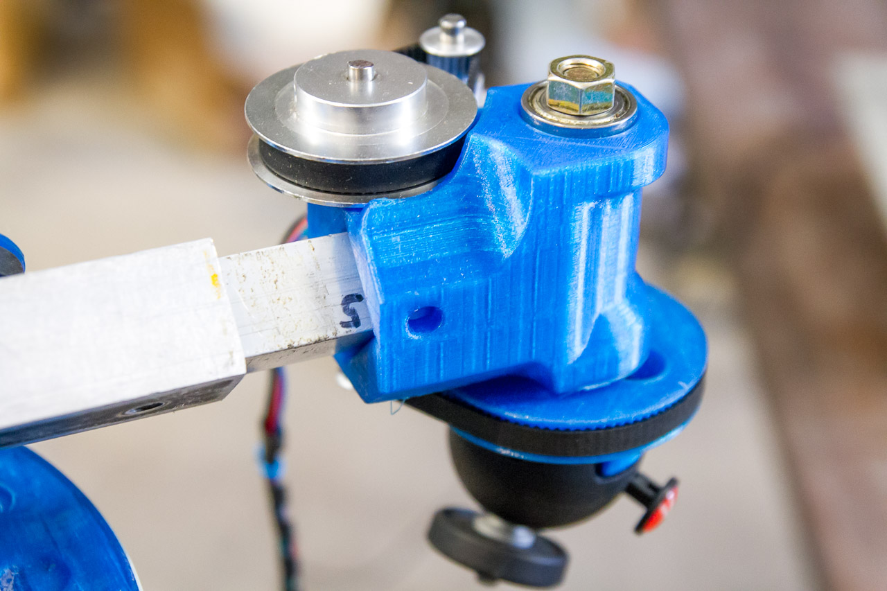
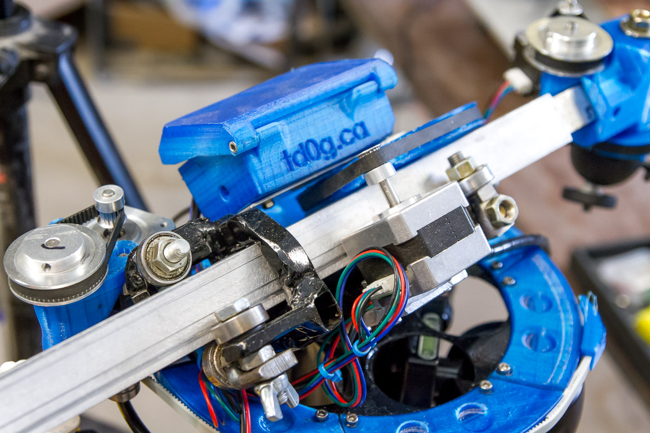
Here’s a few component views of the primary rotator. The boom arm slides through a series of bearings. The boom extension drive turns one of the front bearings. Eventually I added a third front bearing to keep pressure on the drive bearing when the boom is retracted.
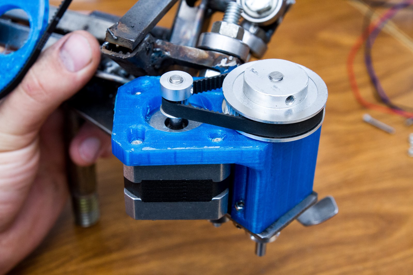
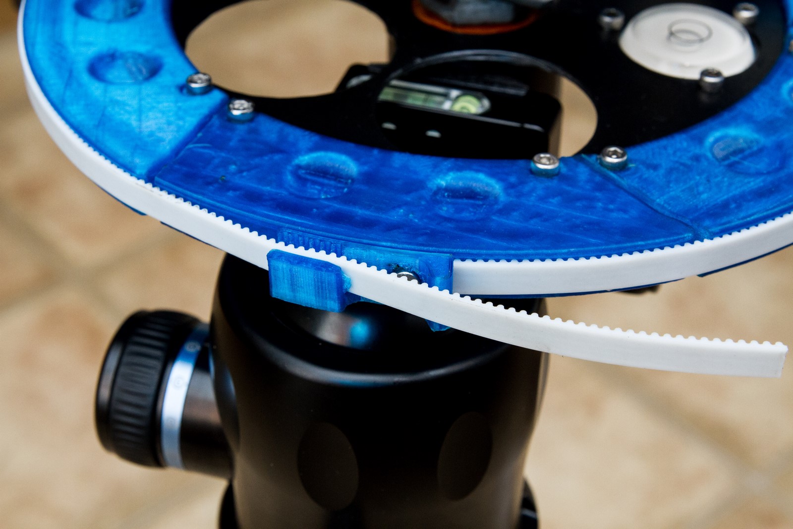
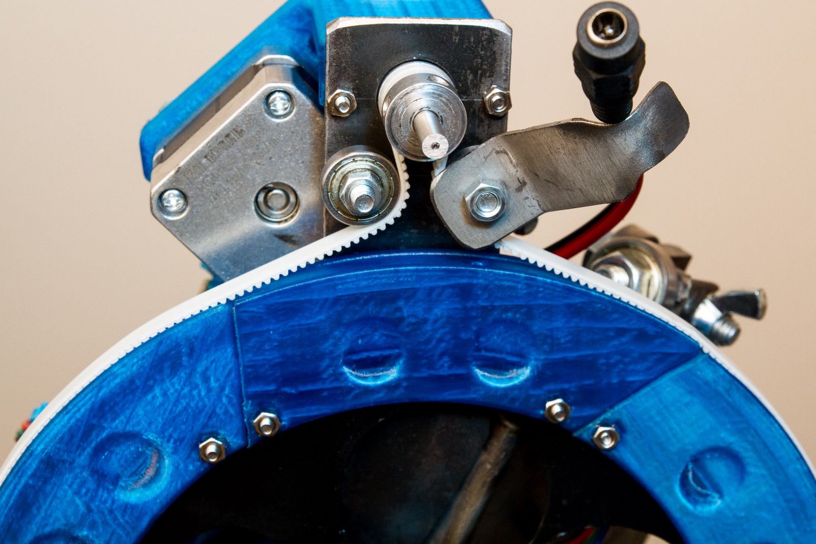
The primary rotator drive is a small Nema-17 motor with a 16:60 reduction drive turning a 20-tooth pulley. A steel-core GT2 belt fixed to the primary rotator pulley goes around a couple bearings and the 20-tooth pulley. Since the belt isn’t closed-loop, the primary cannot do a complete 360-degree turn. Just a minor annoyance and something to keep in mind when setting it up.
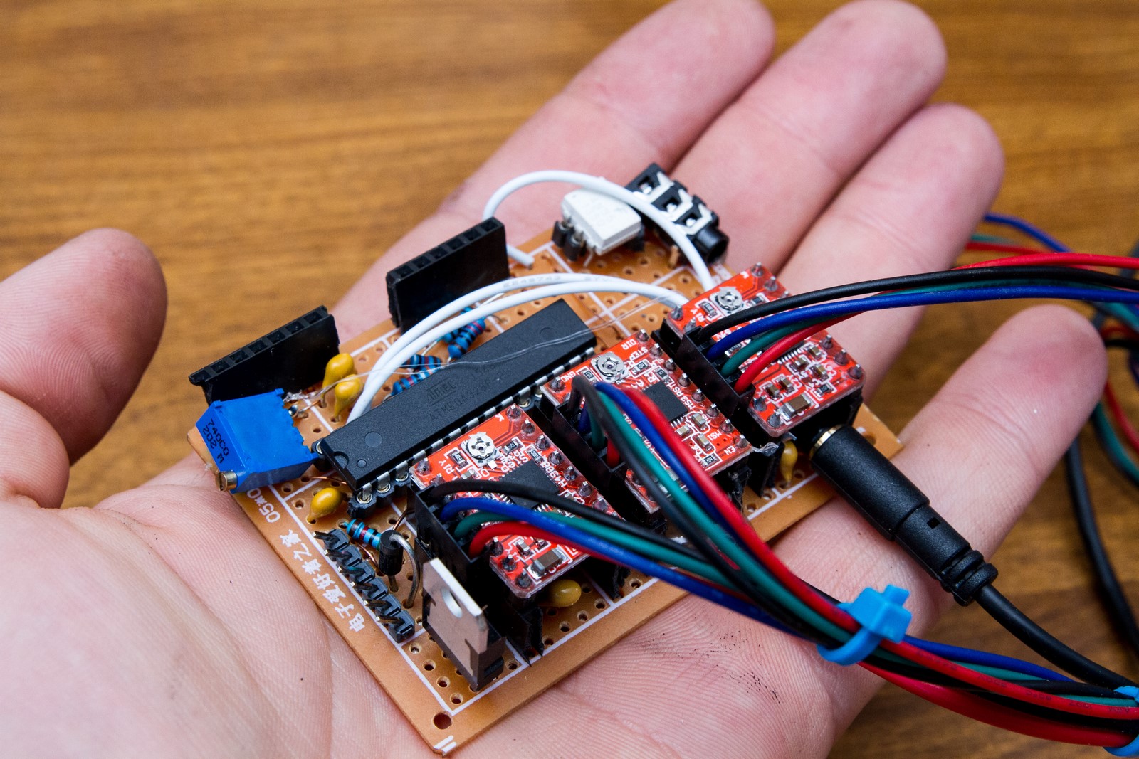
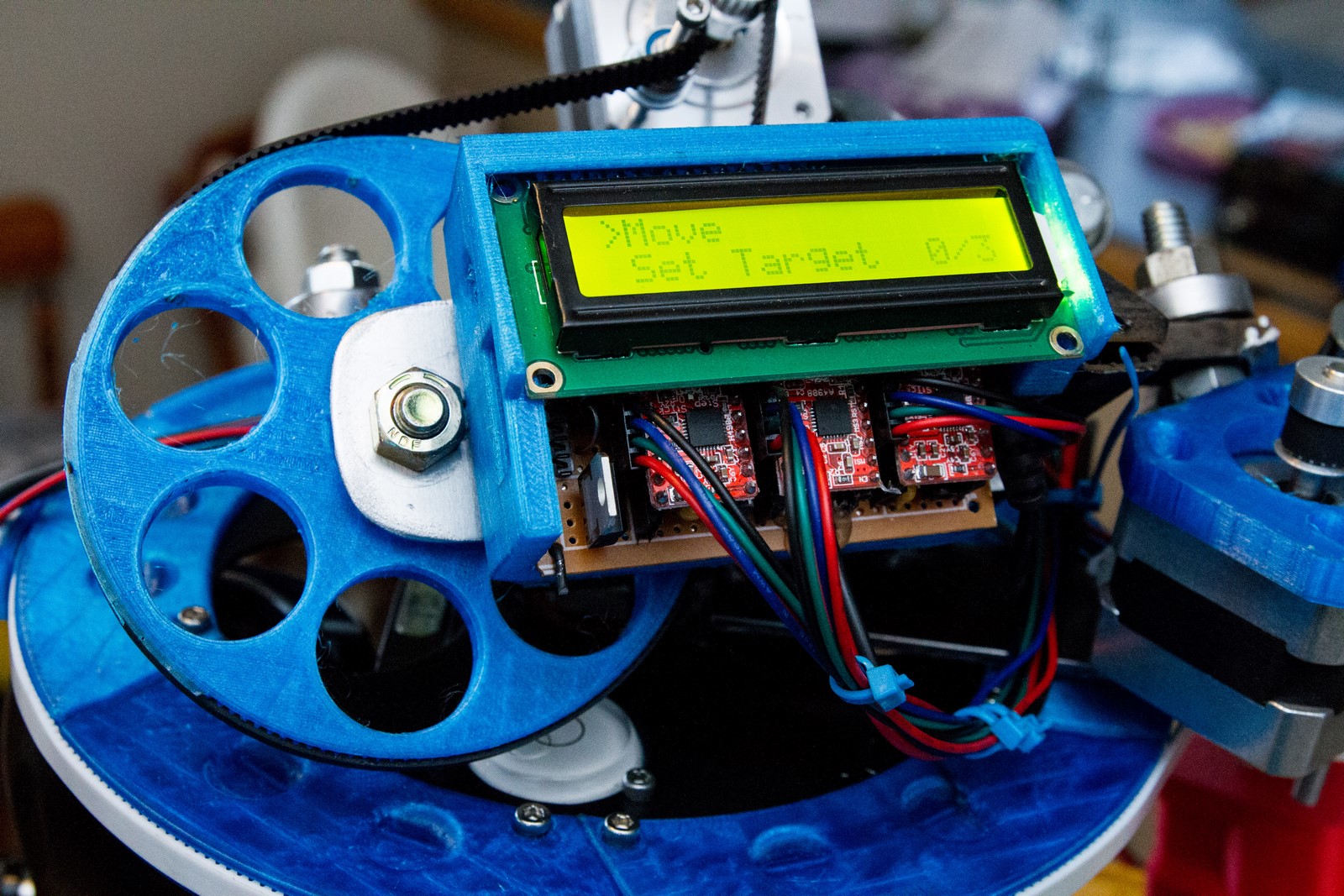
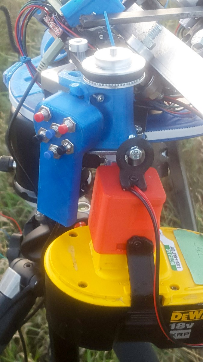
I built a custom controller unit (described in further detail below).
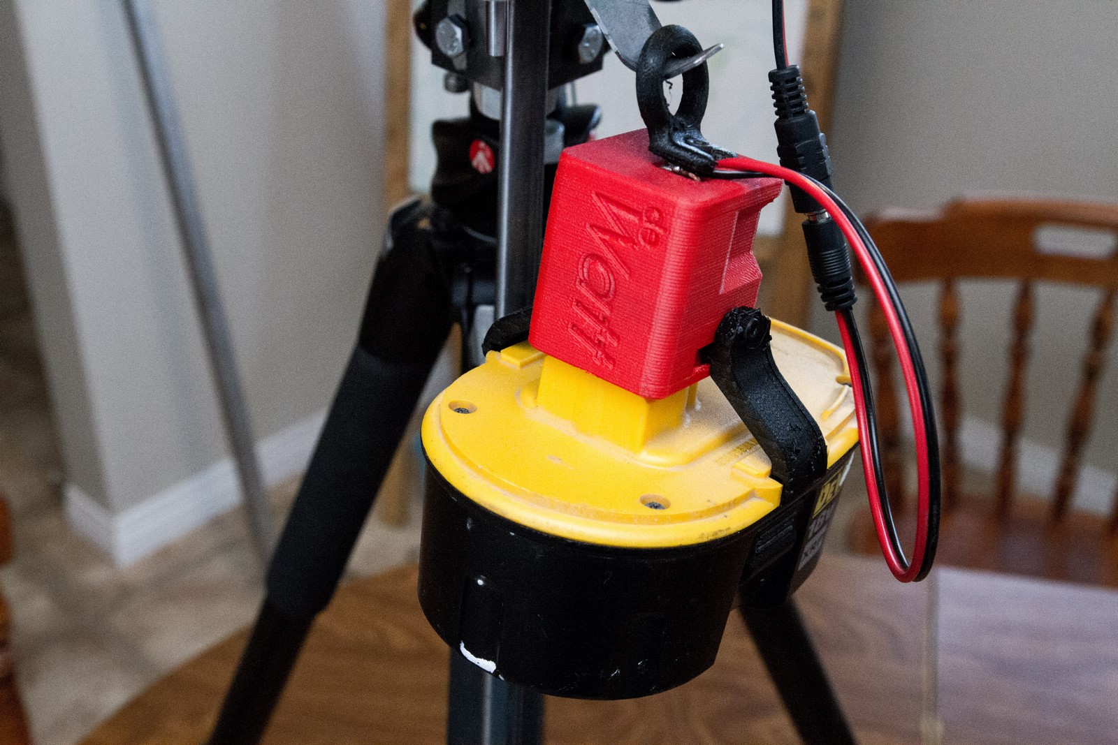
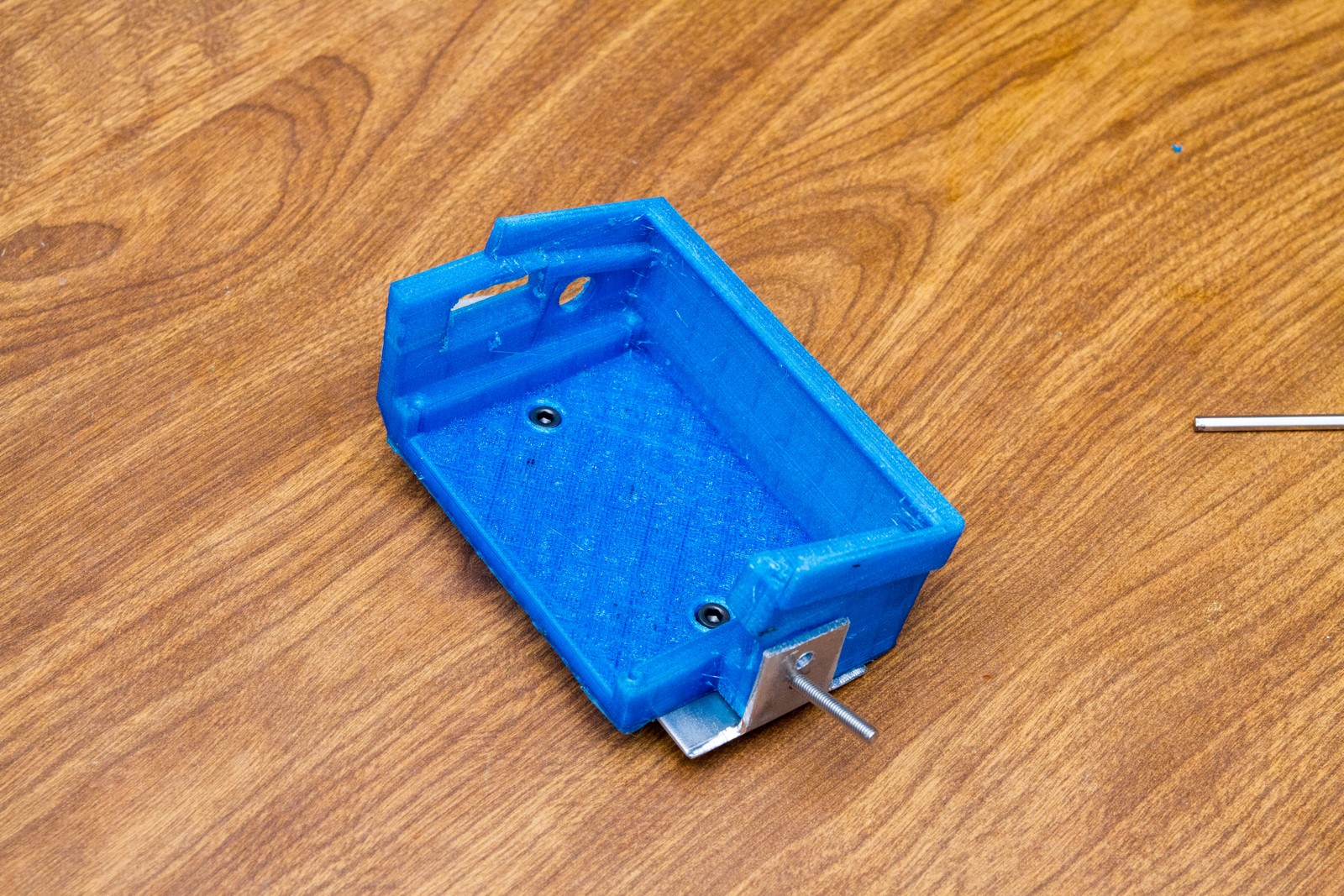
The slider is powered by a DeWalt 18v battery using the DeWatt battery adapter I designed. This adapter is the cat’s meow for many projects requiring a decent amount of mobile power. The A4988 motor drivers like having 18v and sip about 0.5A from it when all motors are enabled. An LM7805 regulator brings the voltage down for all the other components.
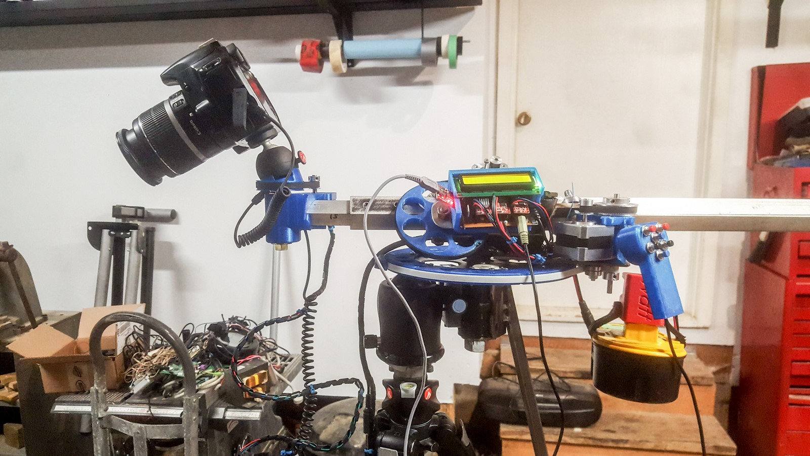
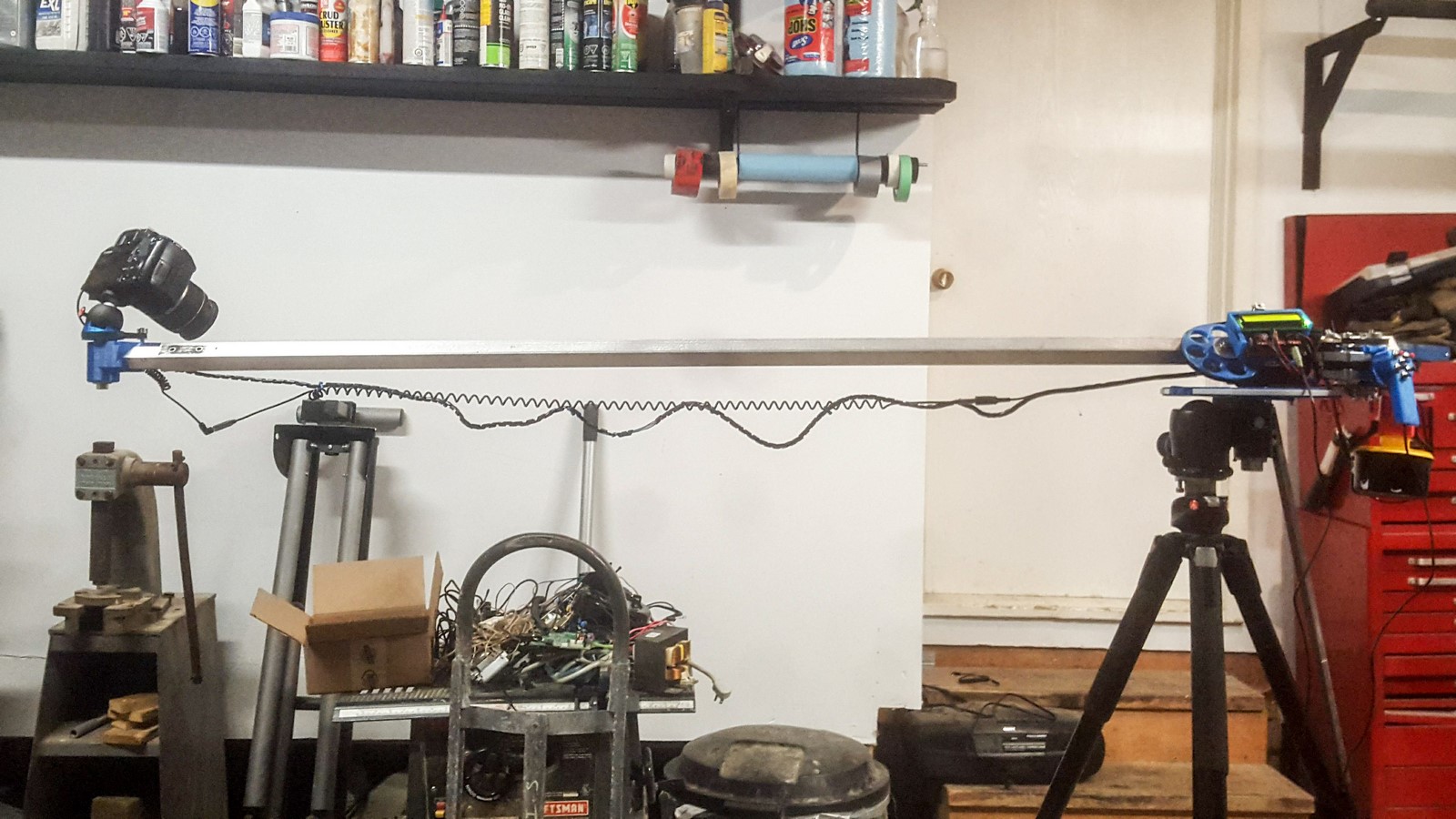
The 1″ aluminium square tube used as the boom positioned in the slider. Originally I used a 3/4″ aluminium square tube, but found it was lacking rigidity. The 1″ is barely sufficient once it is fully extended with my Canon 7D and a decent lens. A coiled 3.5mm speaker cord connects the camera’s shutter release to the controller. Unfortunately the secondary motor wires aren’t coiled so I just zip-tied them to the coiled cable. Note the stabilizer bar on the back of the slider – described in detail below.
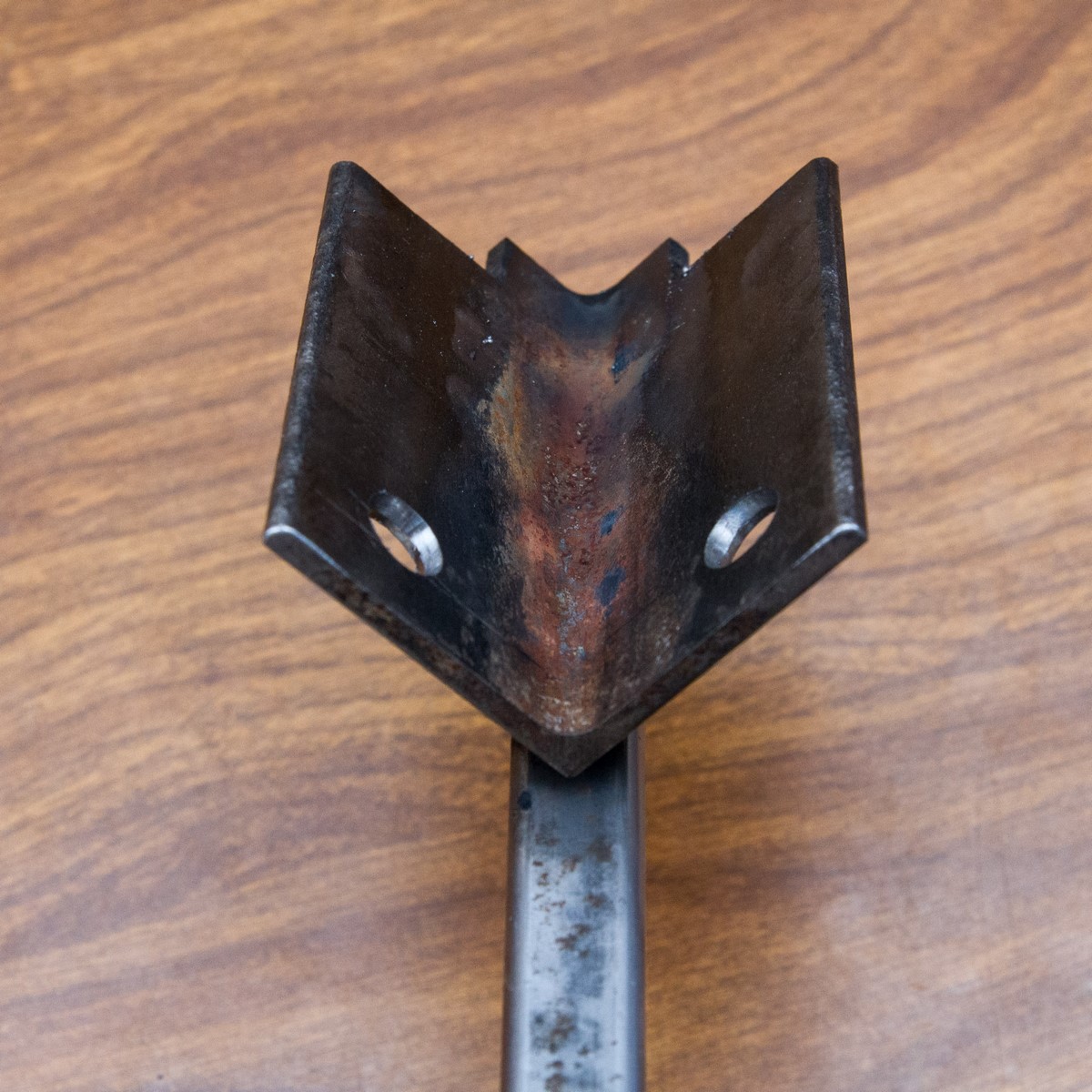
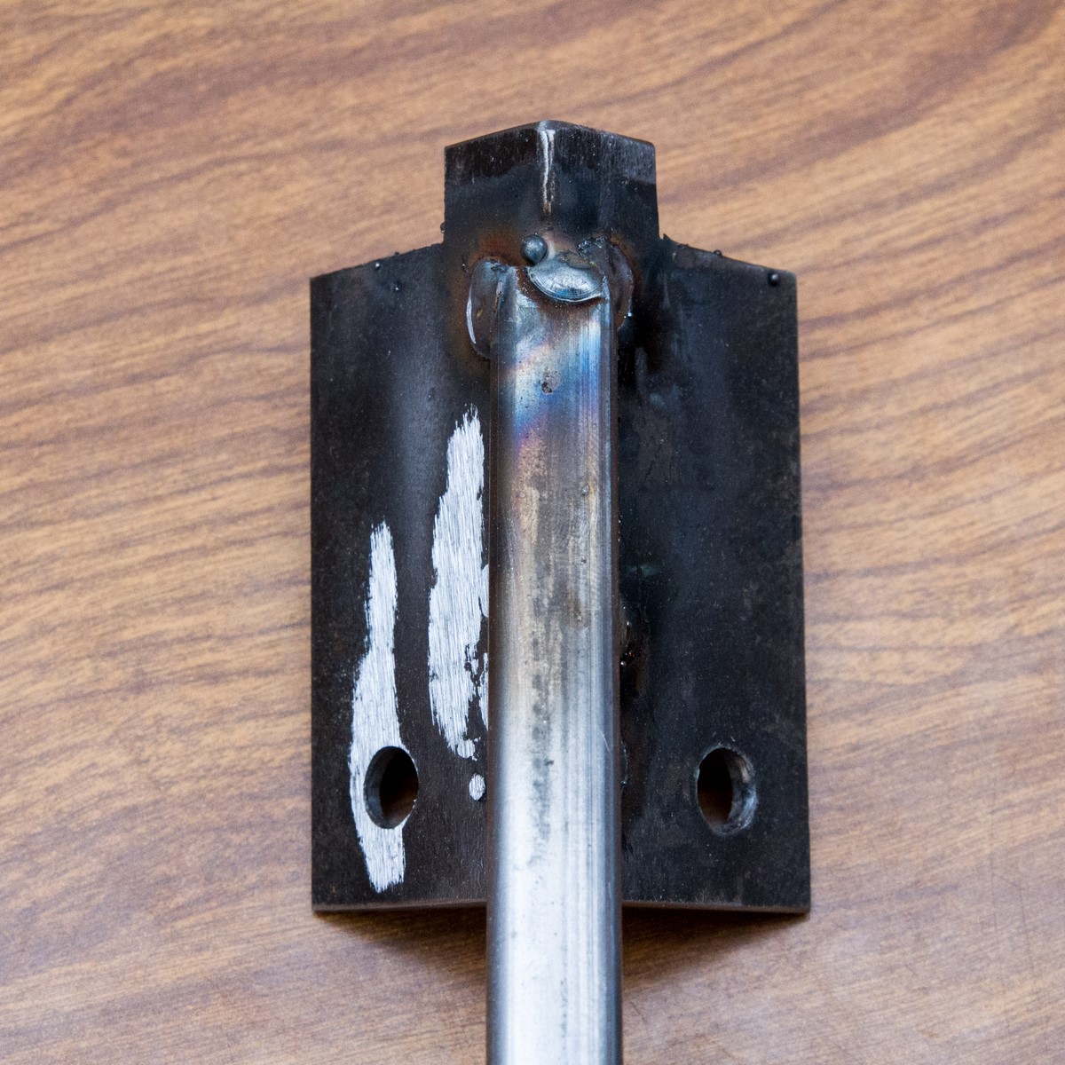
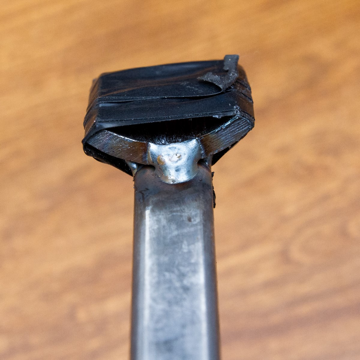
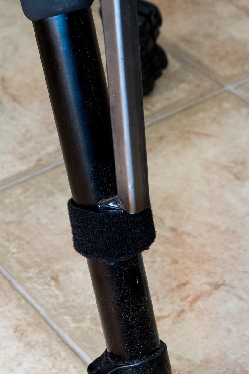
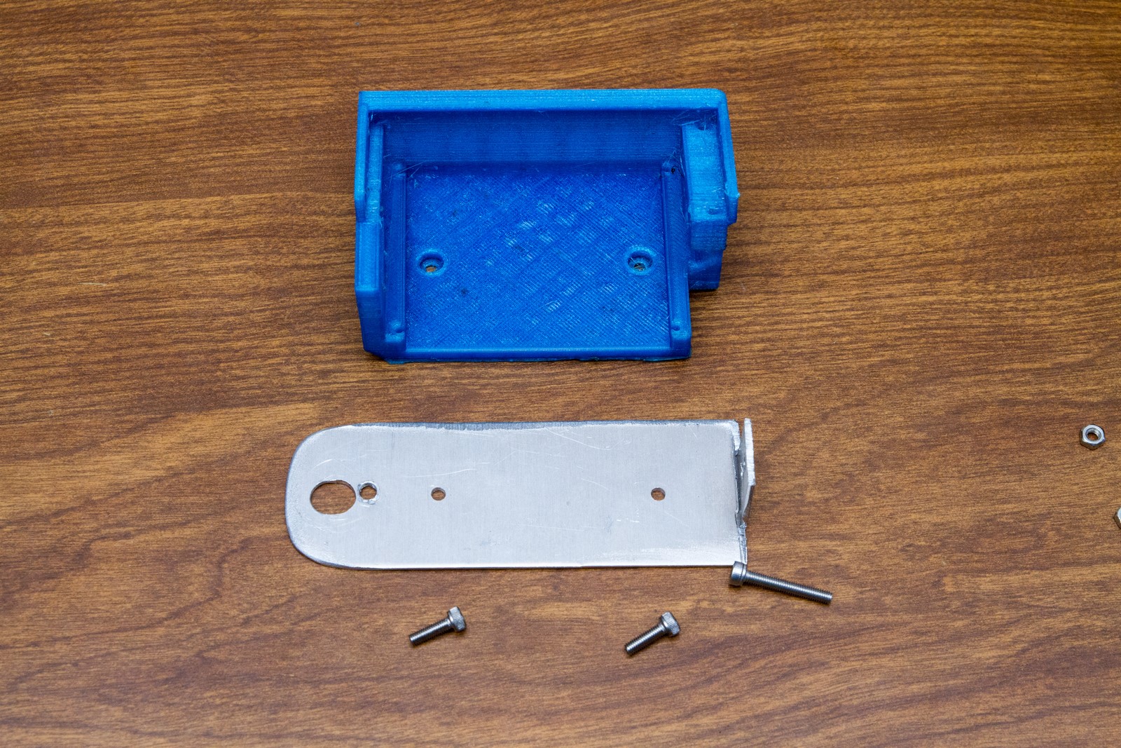
Close-up photos of the stabilizer bar ends. It locks into the primary rotator base easily and fastens to the tripod leg using velcro straps. The bar also splits into two so it can fit inside the storage box.
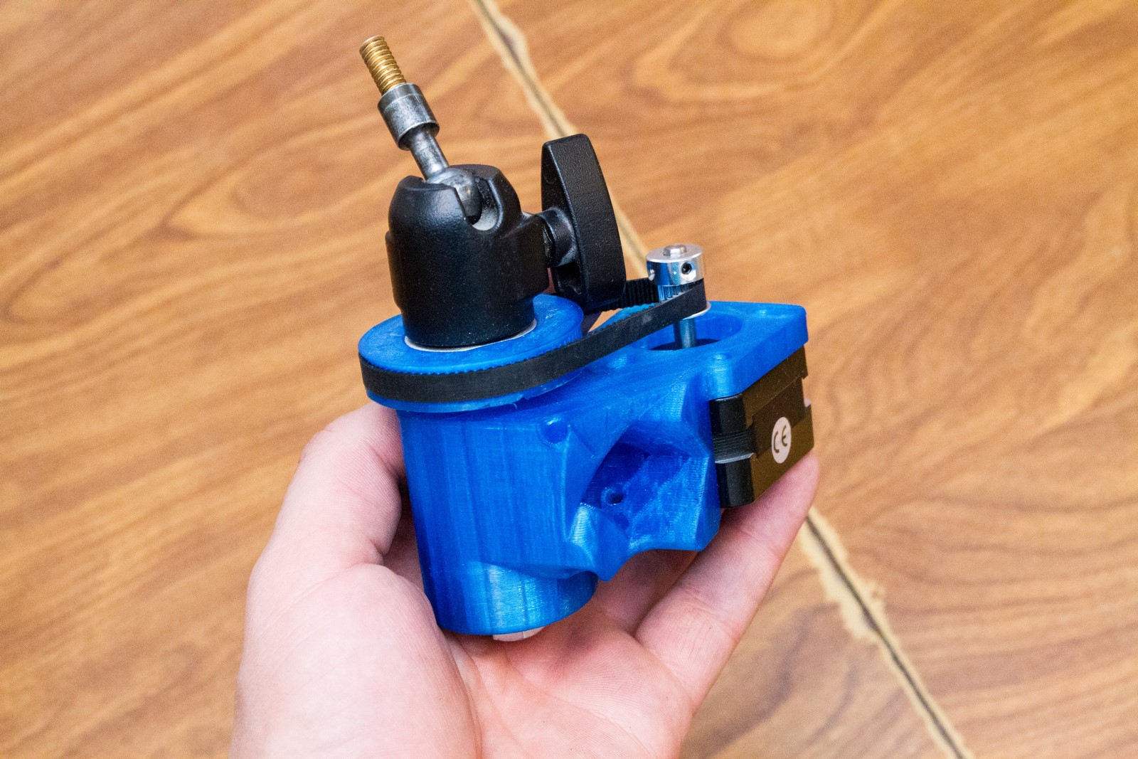
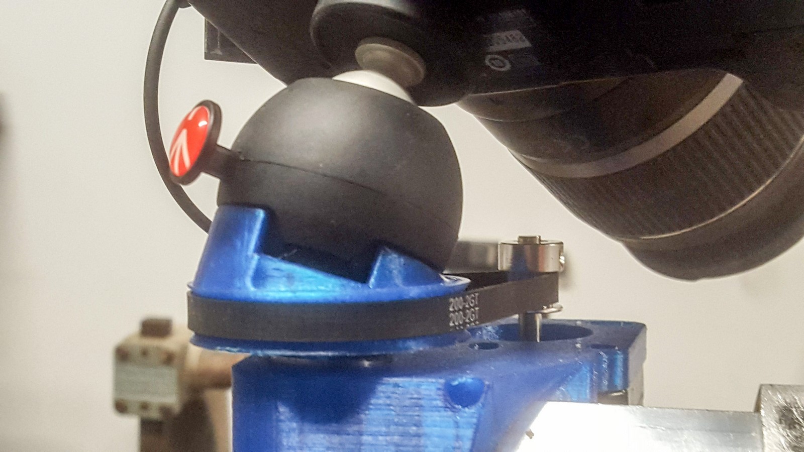
The secondary rotator mounted on the end of the boom. I started with an old ball head, which was horrible to adjust. Eventually I decided to gut a Manfrotto PIXI mini tripod I was gifted and never used. The press-to-adjust feature was the bee’s knees for this application! The head was mounted on the rotator shaft at an angle to increase the tilt range of the head. After some testing, I found that the single-reduction design wasn’t precise enough to make smooth timelapses, so I added a second ~4:1 reduction to the rotator.
The new secondary rotator has incredibly fine movement. I can now take timelapses with a 50mm lens on my crop-sensor camera without significant shake.
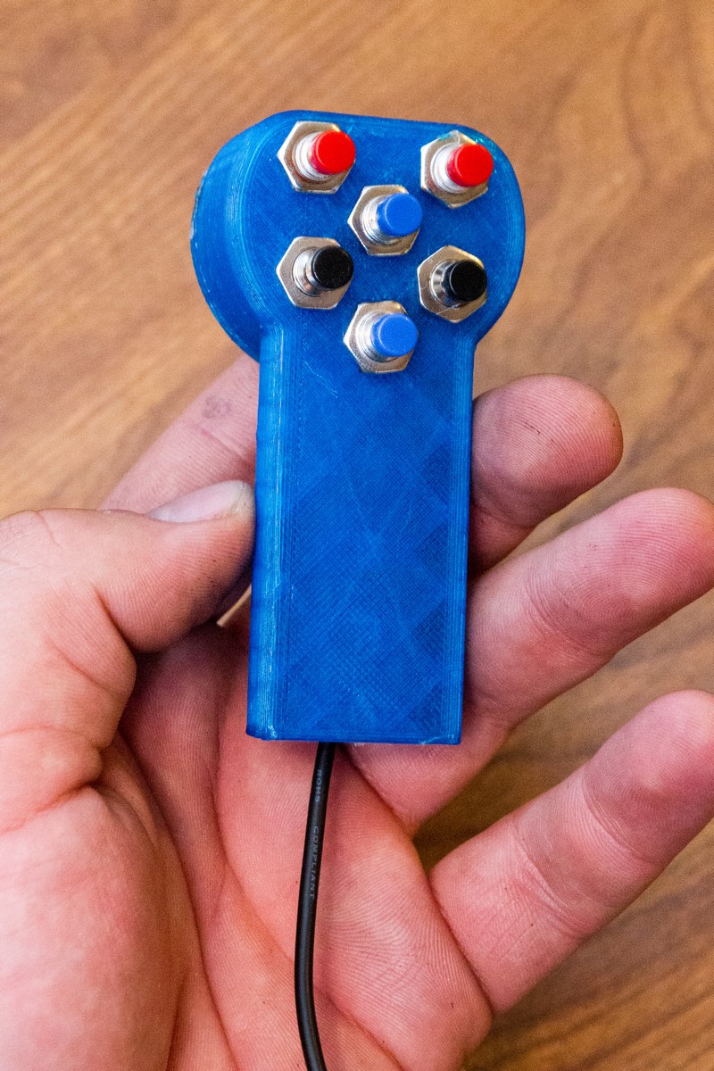
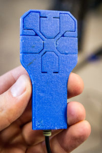
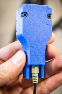
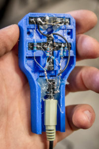
The original remote control (pictured above) was pretty lousy because the switches didn’t have a consistent closed-circuit resistance. This caused many issues since the communication was a simple analog signal. Its form factor was fantastic and the 3.5mm jack made it easy to disconnect, swap out the cable, etc. I later overhauled the remote so that it uses internal microswitches. The new remote came out really good (and it’s available on Thingiverse)! It’s small, nice to hold, easy to control with gloves on, and very reliable! There are only 2 parts to 3D print and the switches are installed without extra fasteners.
CONTROLLER & USER INTERFACE:
The controller is based on an ATMega328p – the same chip you’ll find on an Arduino Uno. I built a custom board for this project, but an Arduino with a custom shield would have worked just as well. The ATMega runs three A4988 stepper drivers, a 1602 LCD, the camera shutter, and a remote control. This conveniently works out use every GPIO pin on the controller. Each stepper driver takes three pins (step, dir, enable) for a total of 9. The parallel LCD interface takes 7 pins. 2 pins for the remote control and 1 for the shutter control.
It was important to have a remote control since the operator must follow the camera around during setup and can’t easily stay at the controller. It is equipped with six buttons (up/down, left/right, and secondary left/right) and is connected to the ATMega by two analog signal wires (conveniently carried by a 3.5mm extension wire).
There are two shooting modes to select from: Inverse Radial (shooting in a circle around an object) and Extension / Eggtimer (moving straight from one position to the next). The Extension / Eggtimer function is easy to use, just move the camera to the start position and select ‘Set Target’, then move it to the end position and select ‘Set Target’. The slider doesn’t care whether the camera moved, rotated, or a combination. It will just move from Xstart to Xend, Ystart to Yend, and θstart to θend (more on these terms below).
The Inverse Radial function is different. The user starts by selecting a target object to move around – and the way to do this is very cool. If the camera can be positioned over the subject then pressing ‘Set Target’ is all that’s required. However, if the subject is too large to position the camera over (eg. a tree), then you can just aim at the object (through the camera’s eyepiece) from two angles and select ‘Set Target’ at each position. The controller can triangulate the object’s location by calculating the intersection of those viewing angles.
After a subject is set by selecting one target (camera positioned over the subject) or two targets (camera aimed at the subject from two angles), the user then moves the camera to the end position of the timelapse. This has the effect of setting θend and DISTobject. Finally, the user can swivel the camera to the θstart position and press Start. The camera will capture a timelapse as it pivots in a perfect circle around the object.

If the total timelapse time is set, then the photos will be taken with an equal interval. The shortest timelapse possible is calculated by the controller to guarantee that each photo has an equal time interval. It is also possible to set the timelapse time to 0, which makes the controller take the photos as quickly as possible. An algorithm decides how long to wait after movement stops for the camera shake to dampen. As the boom extends, the waiting time increases.
SOME MATH:
Now for the most fun part! I wrote an Arduino library to handle the math, so this is just some background for the fun of it.
To make things simple, we want to express the camera position on a Cartesian grid using the coordinates X, Y where X is the lateral axis (moving right is positive), Y is the longitudinal axis (moving forward is positive) and the origin is the primary pivot. Also, the viewing angle of the camera is expressed as θ (Theta), where 0 is viewing directly forward (along the Y axis) and rotating to the right is positive.
In order to move circularly about an object, we have a few additional parameters to express. Xobject, Yobject is the position of the object on the Cartesian grid. DISTobject is the desired distance from the camera to the object. These three parameters remain constant during a timelapse shoot.
The slider’s coordinates are A (primary rotator Position in radians), B (boom extension position in motor steps), and C (secondary rotator Position in radians). Unfortunately the A and C axis’ don’t rotate one radian per step, so the code needs to include a coefficient for these positions (in Steps per Radian). If we use the step length of the B motor as the unit for the Cartesian Grid, then we don’t need a coefficient for the B motor – but we will need a coefficient for the X and Y coordinates to convert them to more understandable units like milimetres or inches. This is important for setting the minimum and maximum boom extension lengths.
So then, the controller needs to perform the following functions:
- Given X, Y and θ, calculate A, B, and C
- Given A, B, and C, calculate X, Y, and θ
- Given two pairs of A, B, and C coordinates, trianglate Xobject and Yobject
- Given X, Y, Xobject, and Yobject, calculate DISTobject
- Given Xobject, Yobject, DISTobject, and θ, calculate X and Y
And here are the equations:
- A = atan(X / Y), B = sqrt(X^2 + Y^2), C = θ – A
- X = B * sin(A), Y = B * cos(A), θ = A + C
- Too much math for this one line – Just read this and see if you can prove it…
- DISTobject = sqrt((X – Xobject)^2 + (Y – Yobject)^2)
- X = Xobject – sin(θ)* DISTobject, Y = Yobject – cos(θ) * DISTobject
Of course there are some things that the library deals with which aren’t immediately apparent. For instance, the secondary rotator position 0 is actually facing directly backward, or θ = pi. Also there are the cases where θ = (pi / 2) + (k * pi), which results in tan(θ) = NAN (Not A Number). The library handles these issues gracefully.
CODE:
The firmware can be found here. It will work on an Arduino, just be sure to set the pin definitions. I didn’t spend much time streamlining the code. It’s bloated, it’s ugly, and it works. The positioning library mentioned above works well.
Shout-out to the AccelStepper library for moving the stepper motors. I love the sound of a stepper motor accelerating! It is also very useful for keeping the primary rotator’s acceleration very low so that the camera doesn’t get jerked too hard.
The analog signals from the controller are measured without blocking the code (analogRead() is never used). This is explained very well by Nick Gammon.
Some basic settings are saved in EEPROM and can be set under a Settings sub-menu. These include A, B, and C coefficients, min and max boom extensions and polarity of secondary motor rotation (useful for switch the camera from top to bottom or vice-versa). These settings can be set in the field so after initial programming, there’s no need for a computer.
Since the slider is designed to work in the field without a computer, hunting bugs could be torturous. To make things easier the code saves data from each timelapse to EEPROM. If a bug appears, the user can connect a computer via UART and re-run it virtually at home. There’s enough room to save the last six timelapse runs in EEPROM, and the oldest is automatically overwritten when a new timelapse is started. When you connect to it over UART, it can retrieve the basic parameters, run the positioning calculations again, and spit it all out CSV form.
FUTURE IMPROVEMENTS:
- Improve the stiffness of the entire assembly – right now it is suceptible to wind shaking. This would require a stiffer tripod, stronger components, and maybe rotating the extending boom 45 degrees?
- Battery monitor – this would require a free analog pin. Right now all pins are used, so I need to make sure the battery is fresh when heading out.
- Improved remote control response. The dual analog channels are fine but sometimes requires patience. Wireless would be awesome!
SAMPLE VIDEO:
Thanks for looking!
Last updated 2020-08-28
3 thoughts on “Camera Timelapse Rig (IREnE) #DIY”