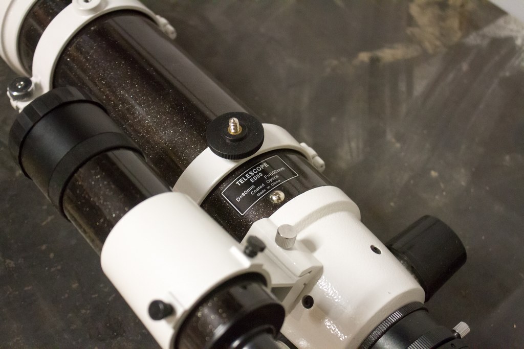
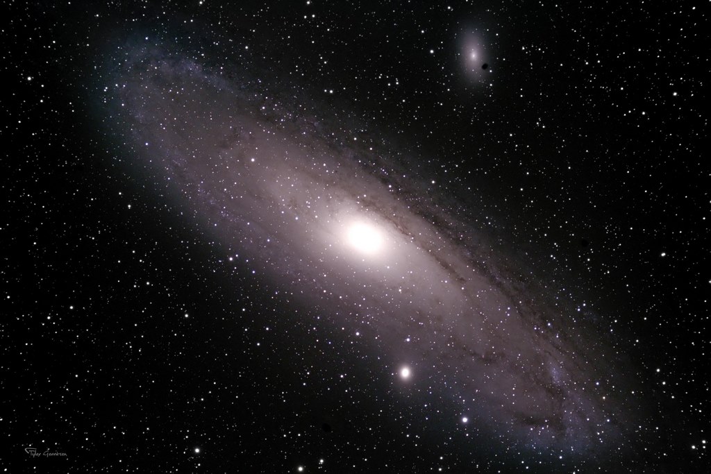
Astrophotography is a bit of a money pit. I recently delved into it with my 80-200 f/2.8L and a home-built tracking mount. It was so much fun that I decided to buy a telescope! So my entire budget went into an 80mm APO.
The problem was that a telescope alone is useless for star pics – some quality infrastructure is needed. This post is about my attempt to affordably build the following components:
- High-precision Tracking Mount with an ASCOM-compliant driver
- Guide camera and scope to help the tracking
- Portable Power supply
- Telescope Focusing motor with an ASCOM-compliant driver
All this adds up – I paid just under $1,000 CAD for my scope and a good mount would cost at least that much. So I decided to try build an astrophotography (AP) setup without draining the bank! It has taken well over a year to develop the equipment, but it has finally started producing good images. Hopefully others can learn from my experience and enter the world of astrophotography without such a massive front-end cost.

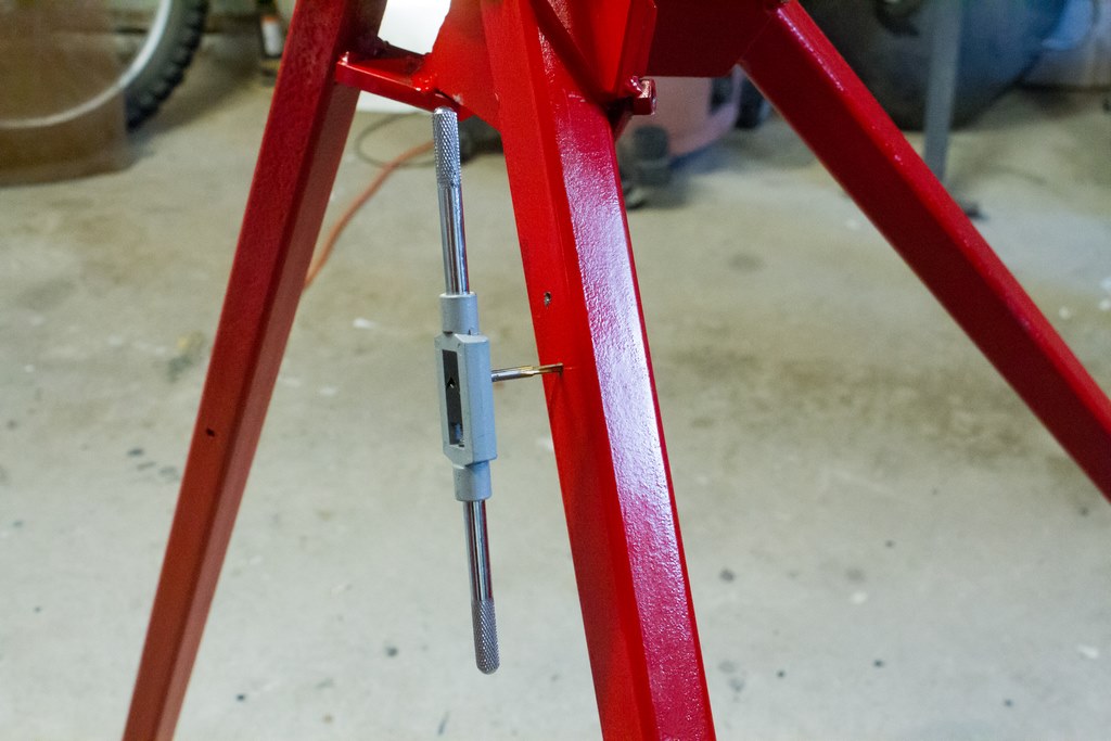
Tripod
A folding tripod with telescopic legs would have been nice, but I can manage without the telescoping part. I used Solidworks on my work PC to develop the tripod to fold up nicely.
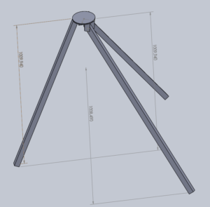
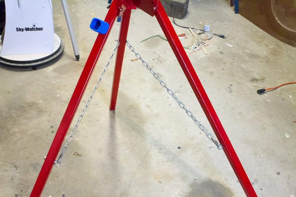
The tripod was painted red to improve visibility under red lights. A 5/16 UNF bolt locks each leg forward. Chains add stability.
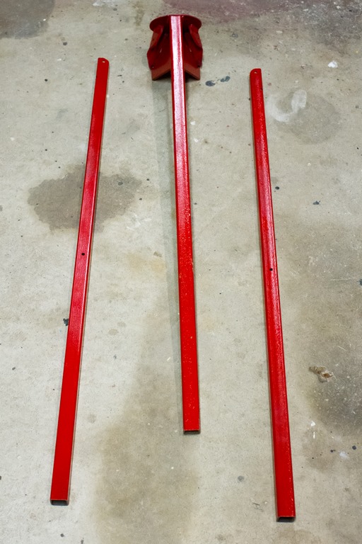
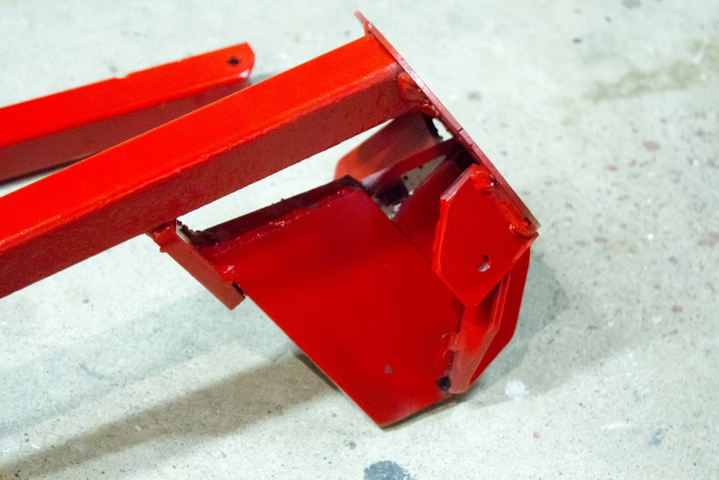
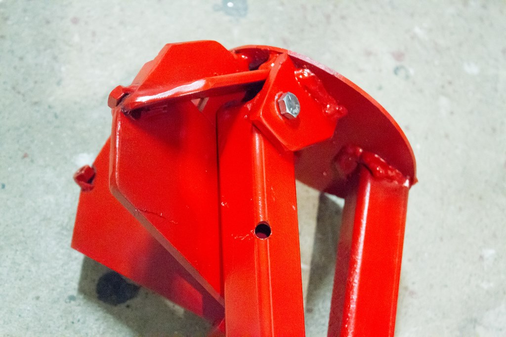

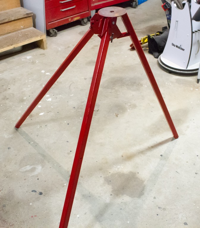
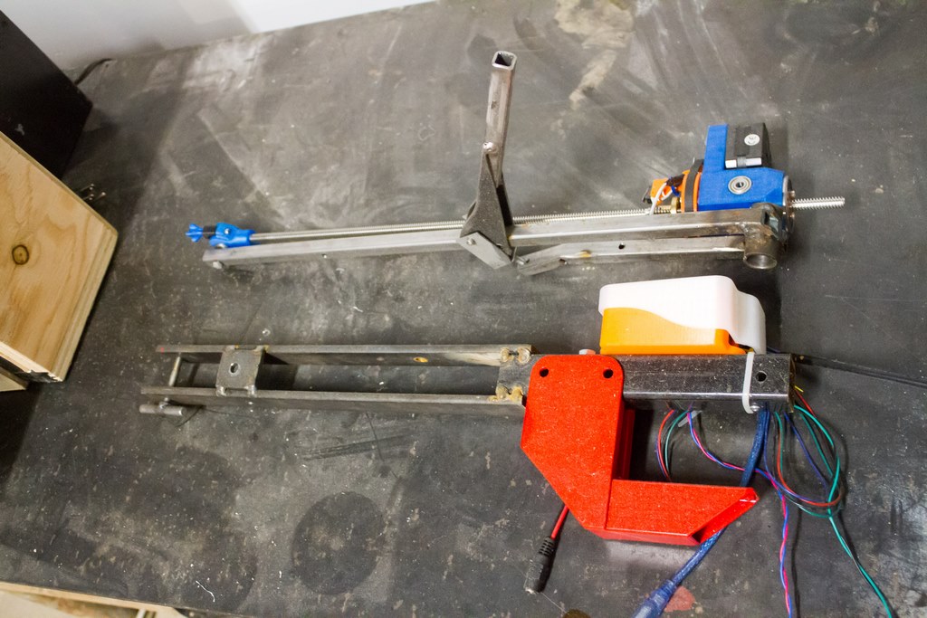
You can see above how it folds nicely. Below it is set up and ready to go. The mount fastens to the round interface plate on the top of the tripod. I didn’t bother painting the top since it will be worn off anyway – maybe some grease will help prevent corrosion going forward. Thinking back, I should have used a thicker interface plate on top, perhaps 1/4″? This thing needs all the stability it can get.


Drive Motors
The Right Ascension (RA) and Declination drives are the heart of this build. Just keep in mind the precision required on these drives. Using my little telescope: 1.5 arcseconds, or 0.0004 degrees, of error is an entire pixel of blur!
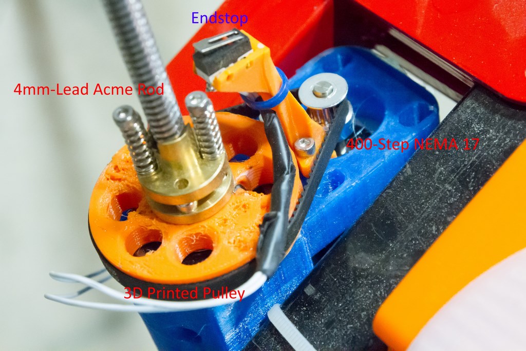
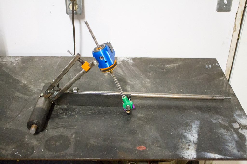
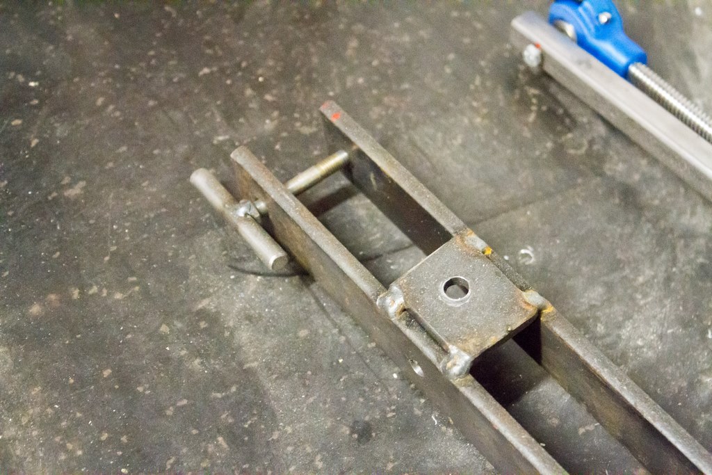
There are several ways to build a telescope mount drive (including manufacturing your own precision worm gear – check out this DIY build from the Curdridge Observatory!) but I’ve opted to use a modified barn-door drive. Each drive has two long arms and a lead screw to push the arms away from each other. NEMA 17 stepper motors drive nuts on the screws by belts (giving the motors an 85:16 reduction). The drives are large and have very limited ranges (the RA axis will only operate for about 3 hours before it needs to be reset), but offer much higher precision than other options I considered.
The STL files for the drive can be found on Thingiverse.
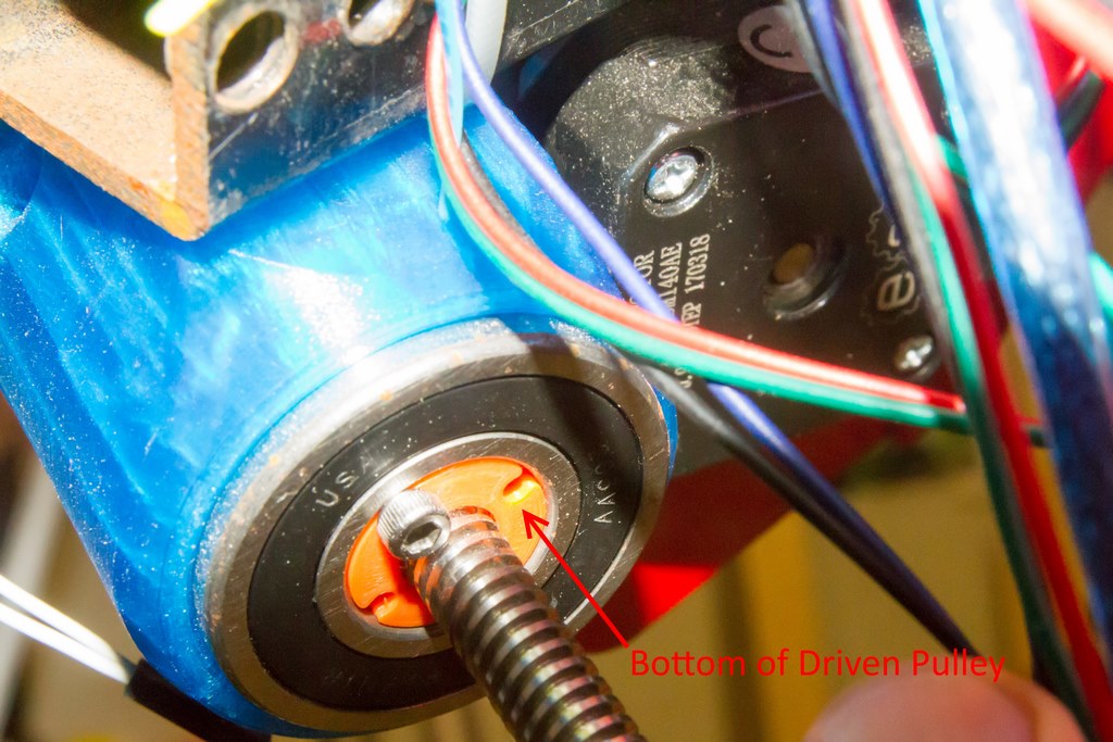
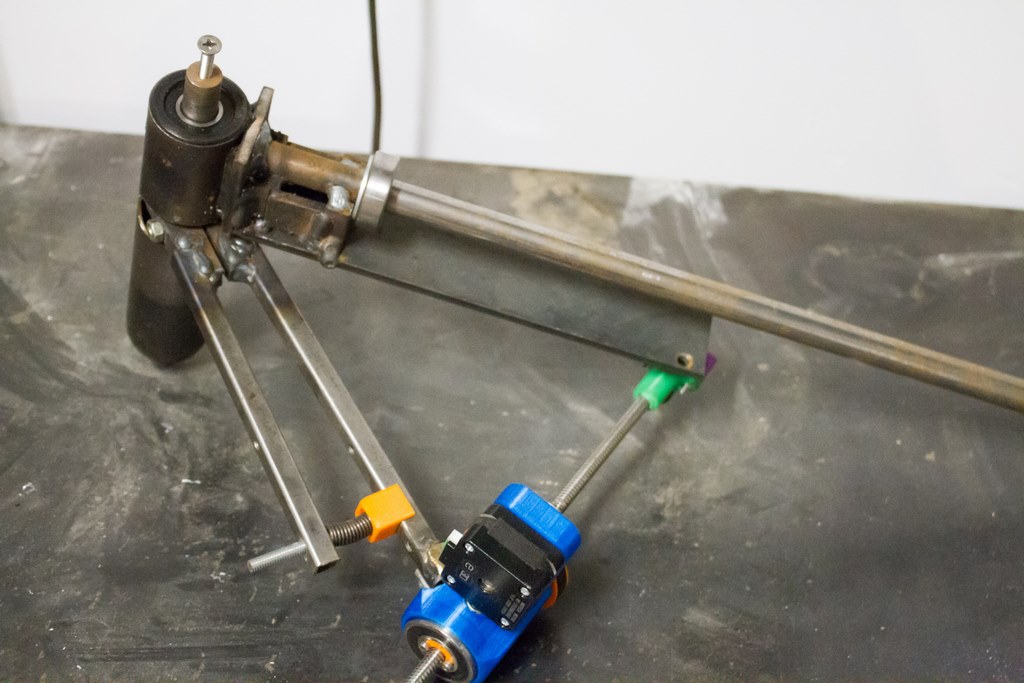
The drive motor is mounted on a 3D printed PETG mount. It turns a 16-tooth pulley and drives an 85-tooth 3D printed pulley. The driven pulley mounts inside a pair of bearings and two ACME nuts screw onto the top.
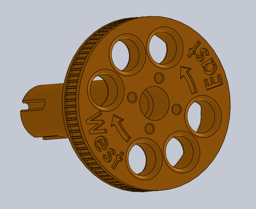
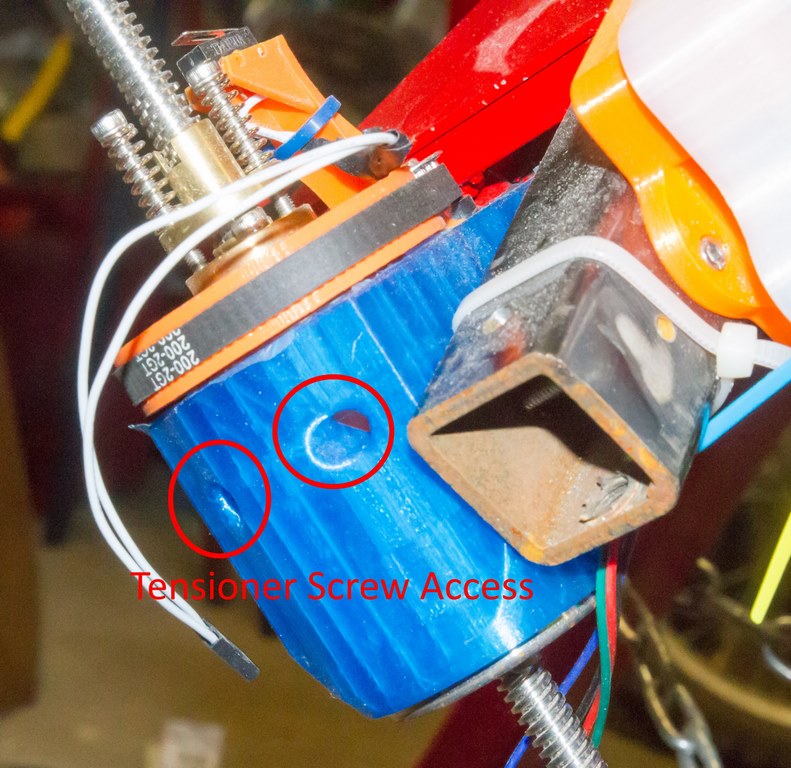
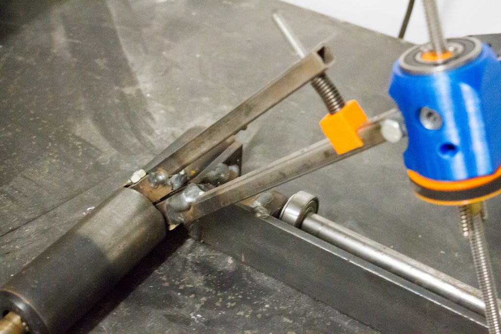
A pair of tensioner screws push the motor away from the driven pulley. Please excuse the poor surface quality of the driven pulley, I attempted to print embedded text into the pulley but failed with the more difficult PETG.
Because there is no linear relationship between the motor drive speed and the shaft rotational speed (because Pythagoras), the microcontroller had to be given a special program to constantly change the speed of the RA drive motor. The declination drive motor has some tolerance for error and is controlled using the AccelStepper library.
The Arduino has a Trig library, but I didn’t trust the accuracy of the library. Instead I built a spreadsheet to calculate a lookup table, which was then loaded into the ATMega’s PROGMEM (Same as my Tracker V2.1). The spreadsheet is available with the firmware.
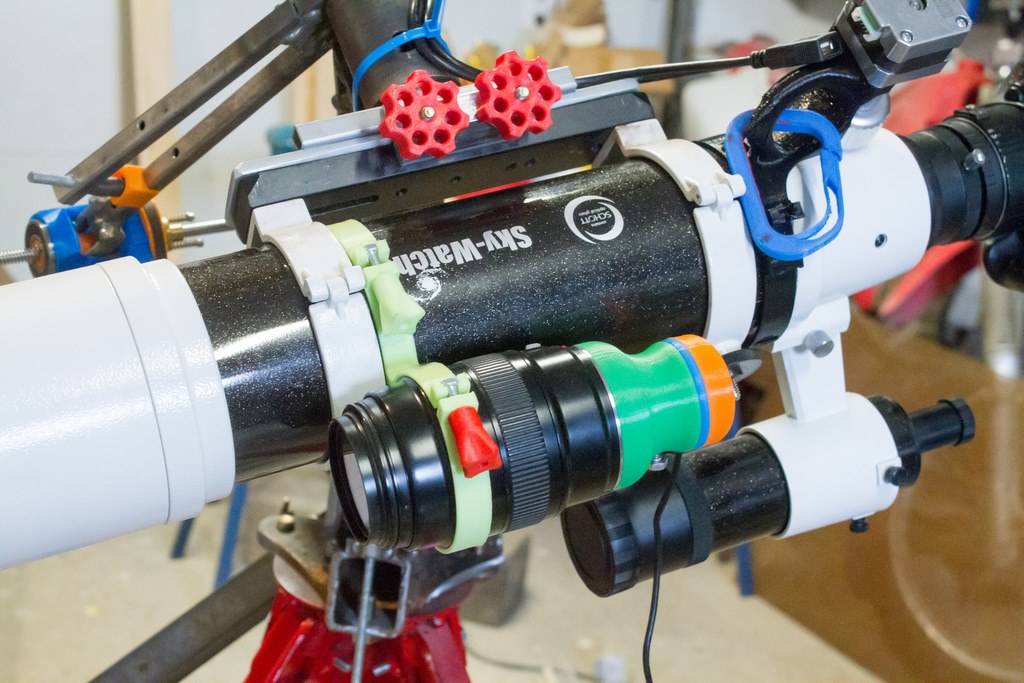
Mount
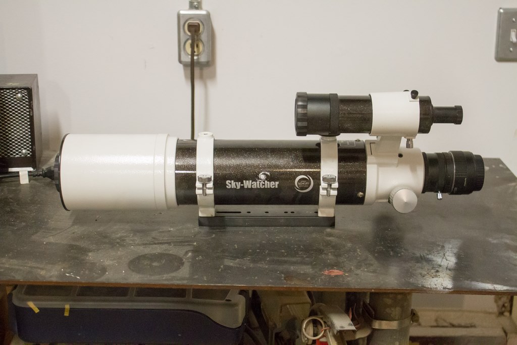
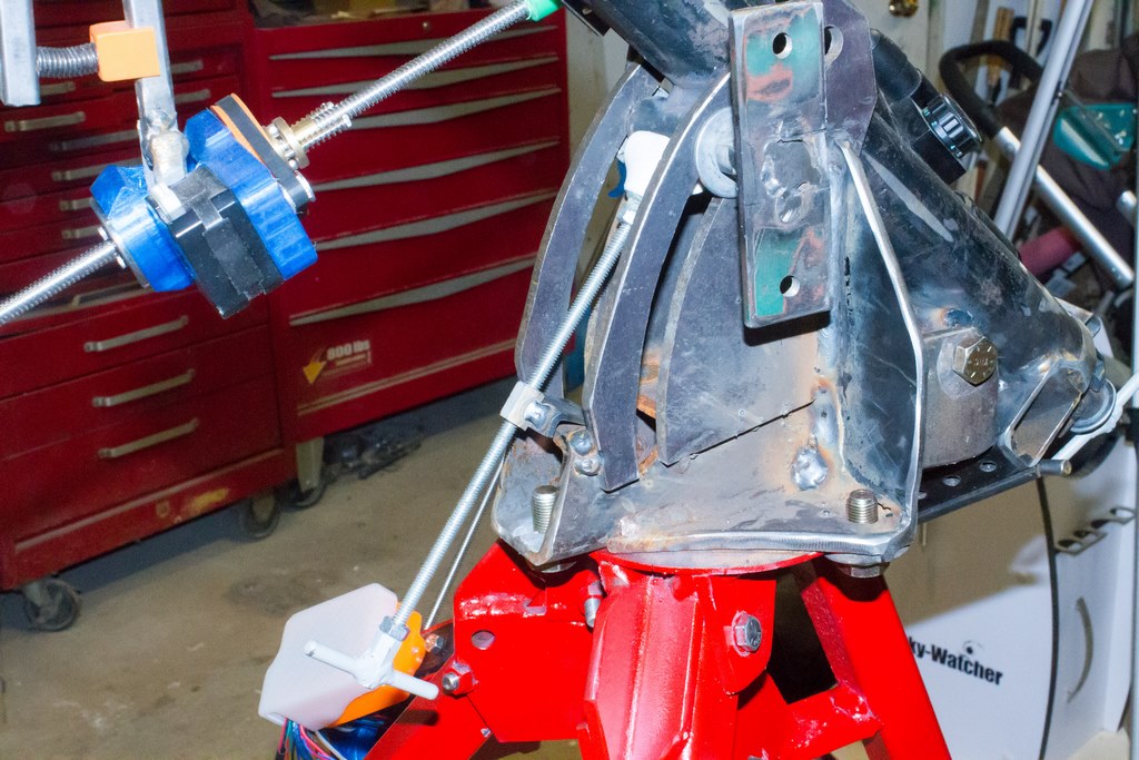
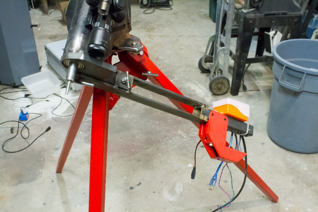
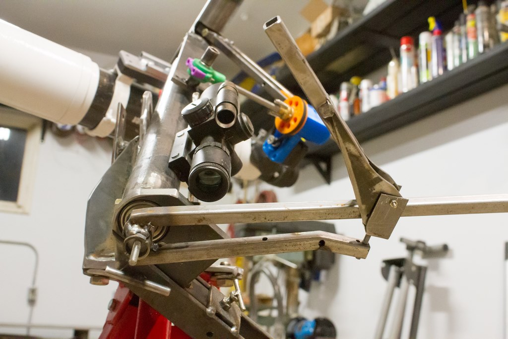
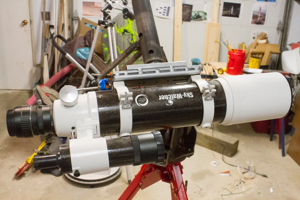
Here’s an overall photo so you can see where all the parts are going. Some parts are painted, some are not. I opted not to paint the parts that are still being optimized.
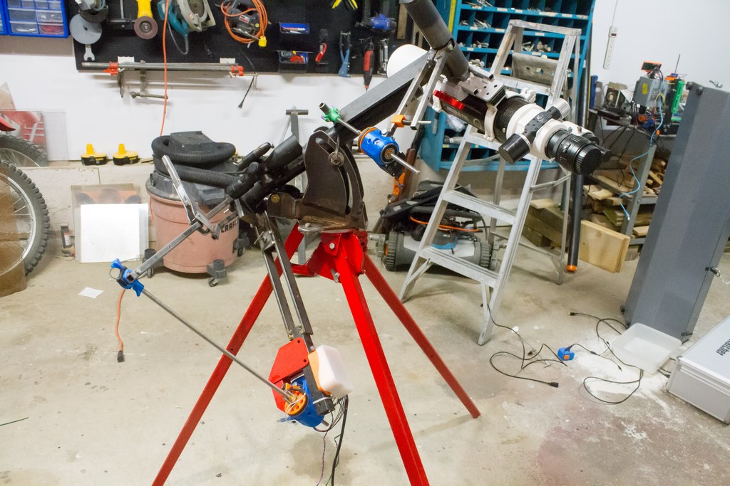
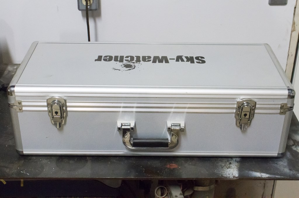
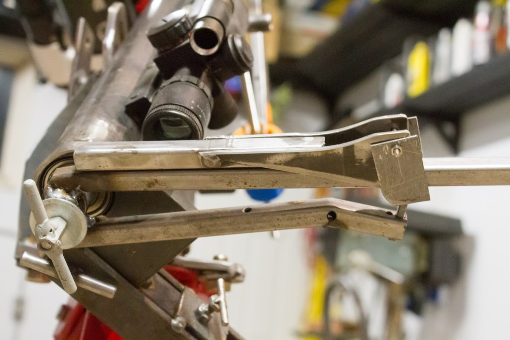
The mount looks cumbersome at first glance. It’s heavy but still manageable. It disassembles and can fit into a 30″ long box. Below are photos of the declination drive attached to the Right Ascension (RA) shaft. The declination clutch can be released by squeezing the spring-loaded arm.
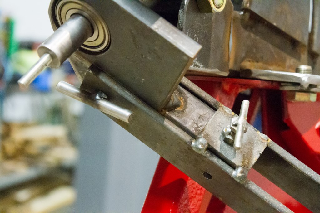
The RA shaft slides into the RA barrel. The barrel is a schedule 40 pipe with sleeves on the ends to hold the bearings. The bearings and shaft were scavenged from a treadmill roller.
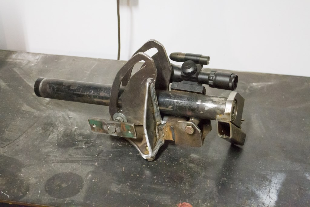

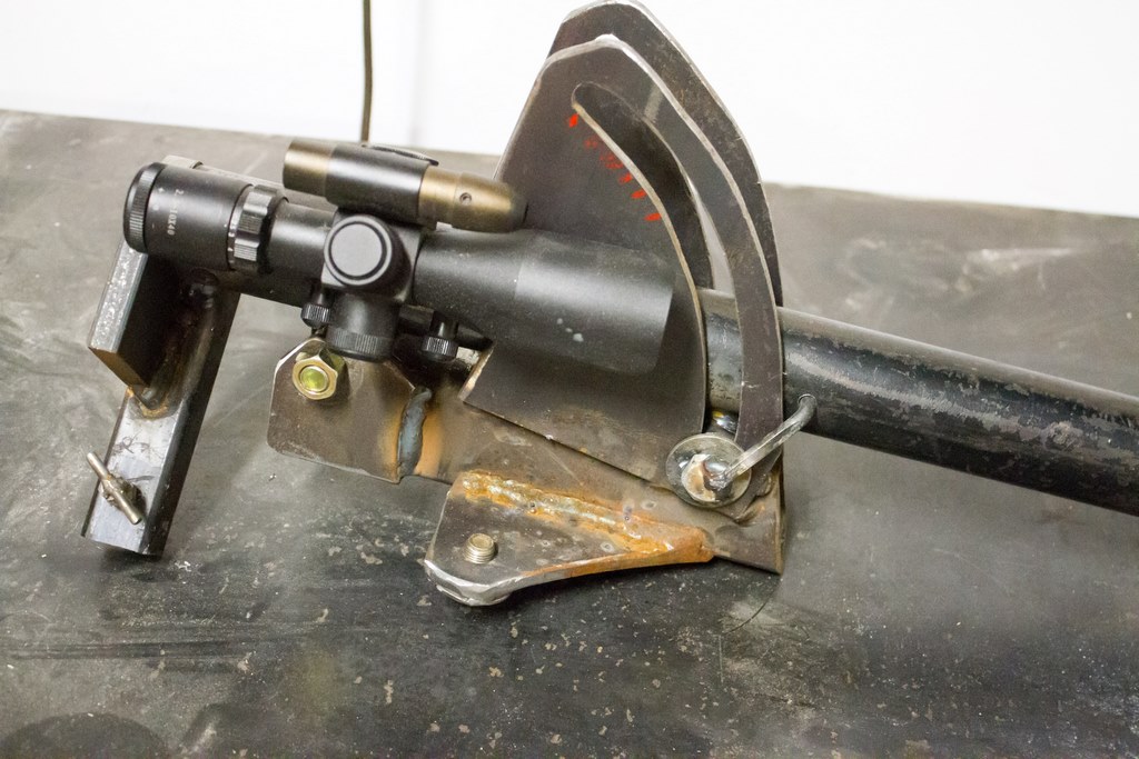
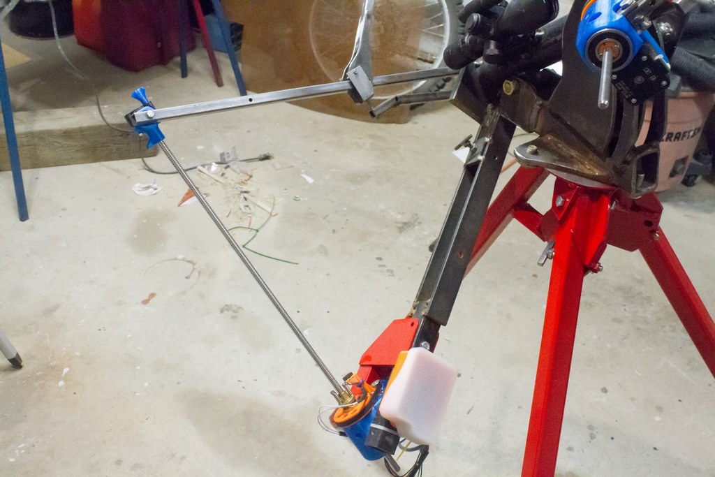
The barrel/riser assembly mounts on the tripod. Notice the rifle scope. Polar alignment is a bit easier with the illuminated reticle. Problem is that I keep forgetting it on and my supply of coin-cell batteries is dwindling…
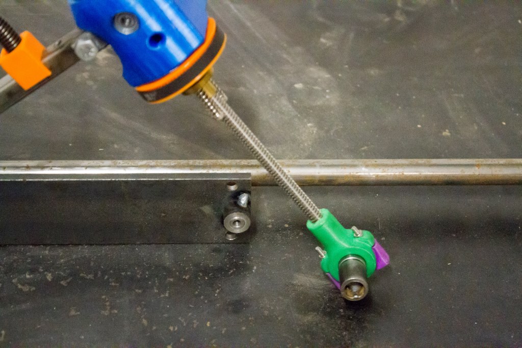
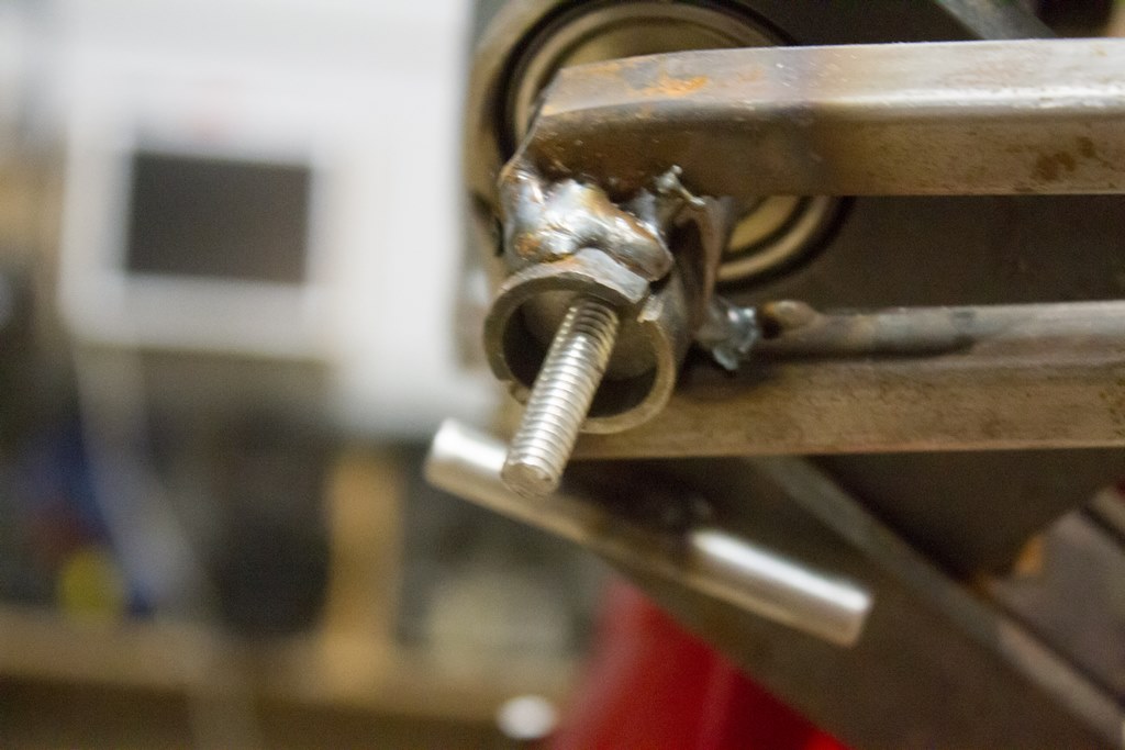
The RA barrel lift uses 1/4″ threaded rod. It is used during alignment, and comes off once the alignment is set.
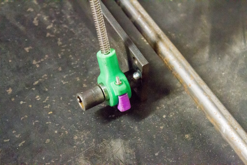
The right ascension drive attaches to the barrel quickly using a few screws. A clamping screw on the red part secures the motor. It looks odd, just keep scrolling to see how it all works together.
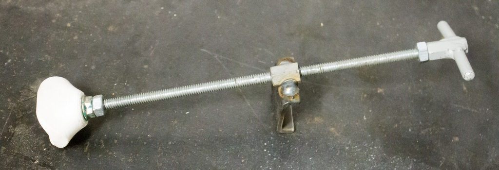
The driving arm slides onto the right ascension shaft and is secured with a wing nut.
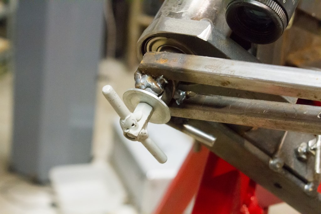
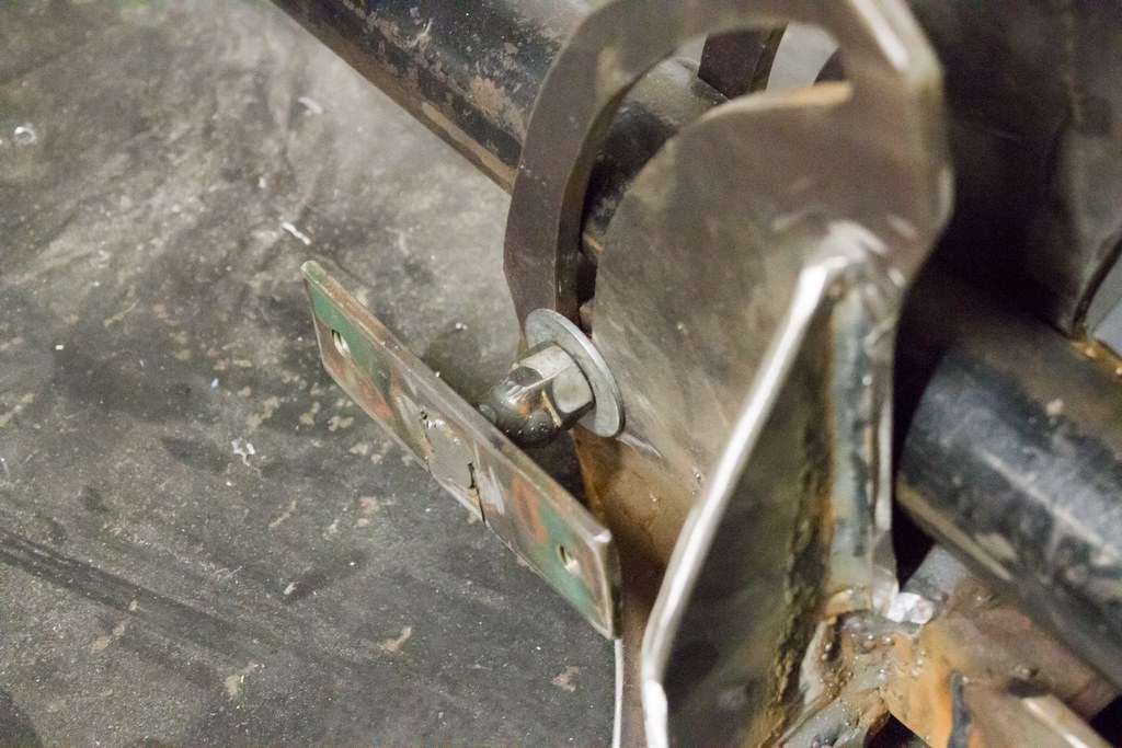
Here’s the right ascension clutch. Since the drive is limited to only a few hours of tracking, most of the slewing is done manually by releasing the clutch and manually aiming the telescope. The clutch is an over-centre with a magnet to secure it in the locked position.
Here it is in the released position. This is an easy clutch to build, but unfortunately it rotates the RA axis just a bit west when I first engage it. I can compensate by aiming slightly east or slewing east after it’s engaged.
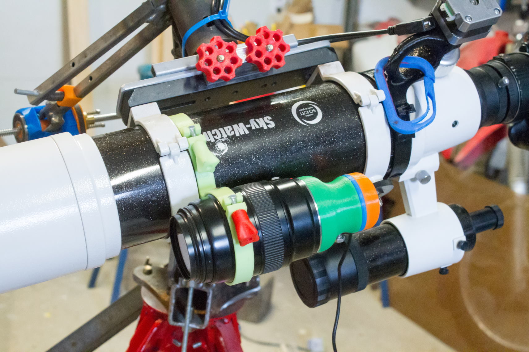
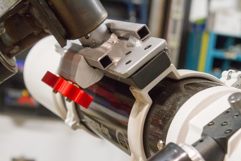
The telescope gets mounted on the end of the declination shaft. I used to have the scope’s mounting rings bolted directly onto an adapter plate, but this was annoying as I couldn’t quickly remove the rings.

Telescope Ring Dovetail Clamp
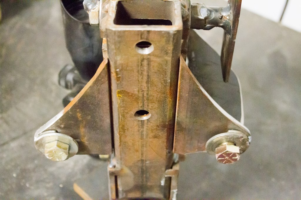
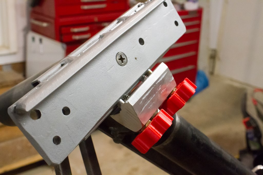
To make life much easier, I built a dovetail clamp that bolts onto the declination shaft.
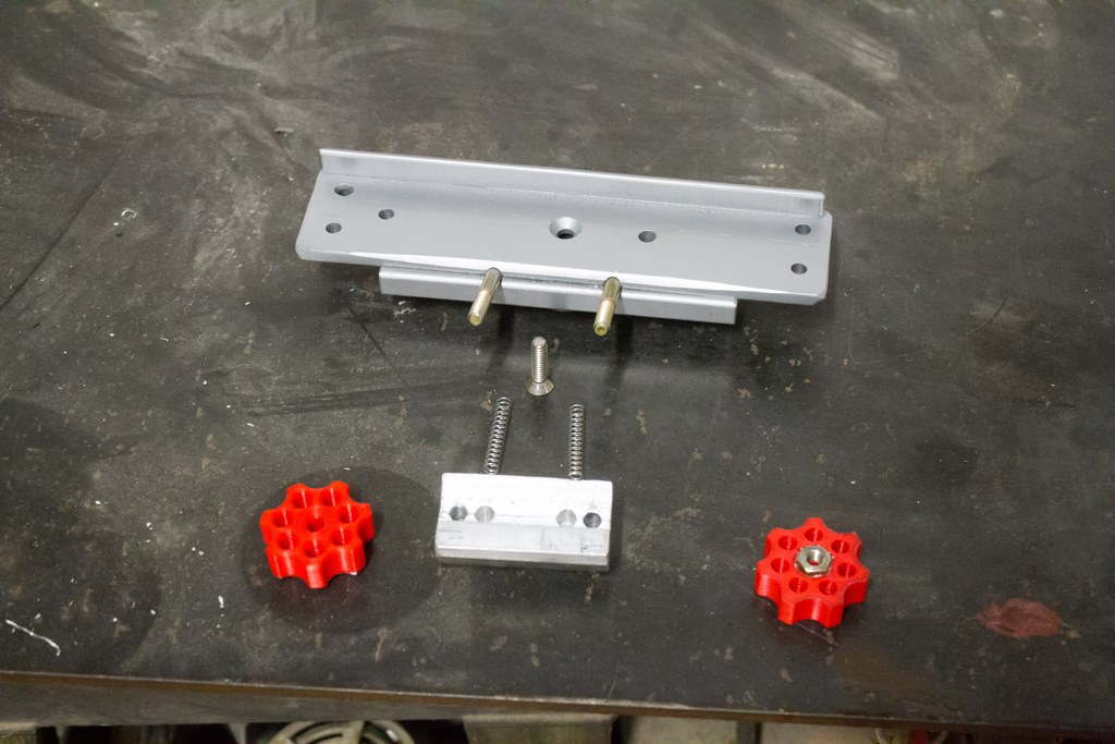
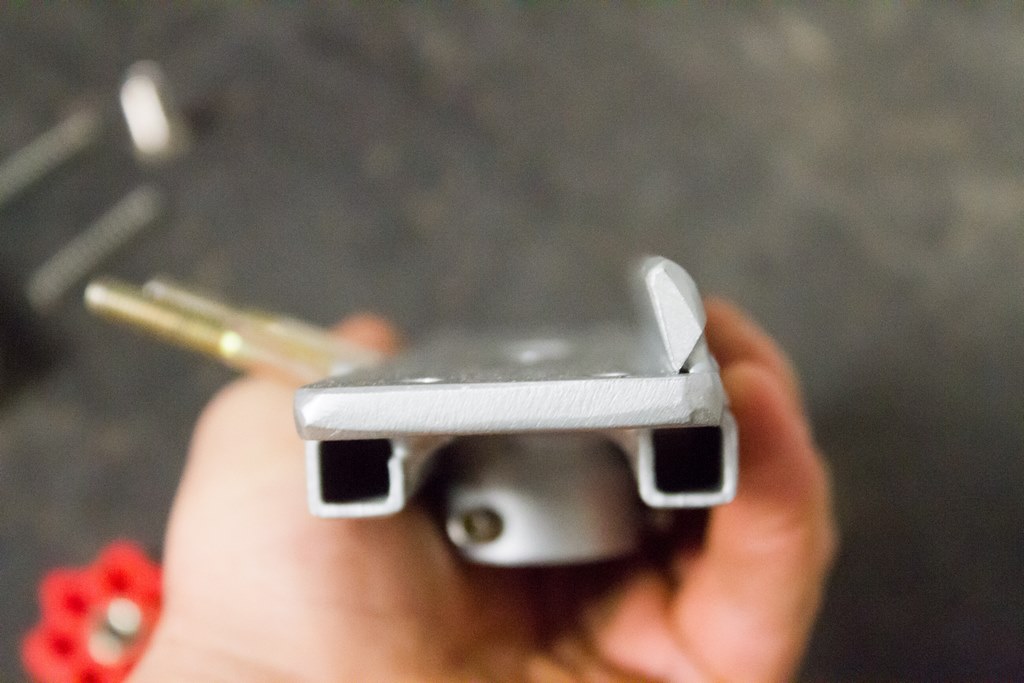
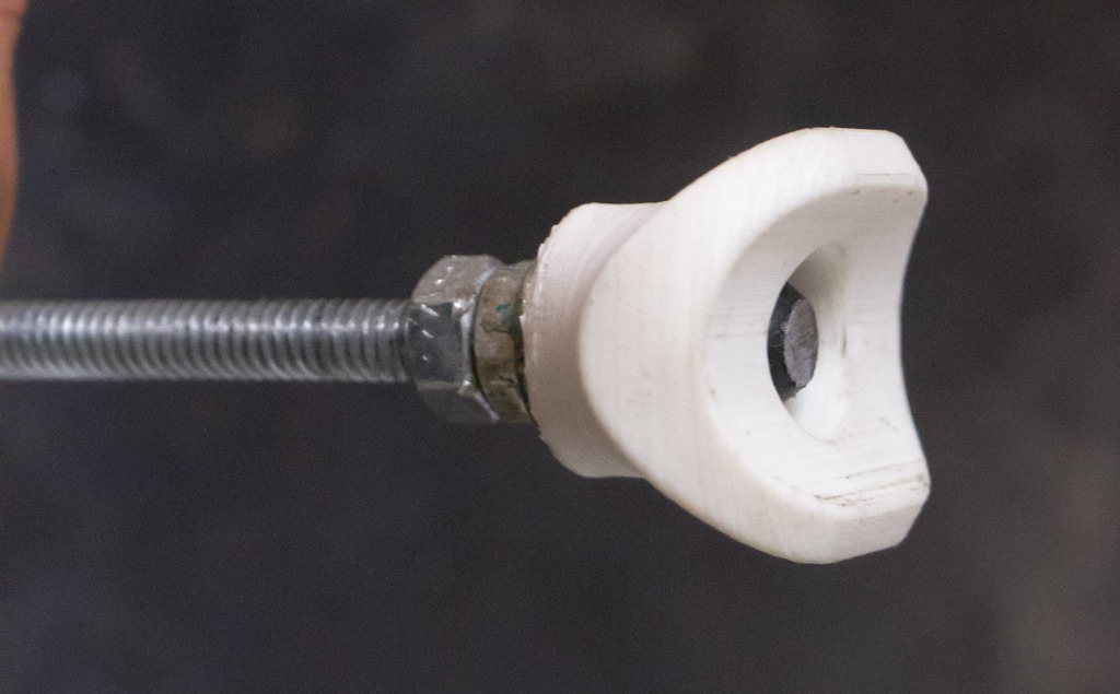
The clamp base plate is all steel. Two 1/4″ UNF studs protrude from the side. A machined aluminum clamping block slides on the studs and are tightened by a couple 3D-printed knobs. Two small springs automatically open the clamping block when the knobs are loosened.

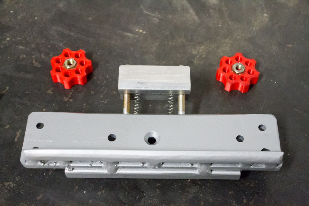
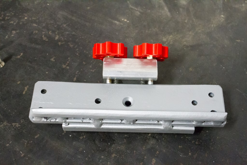
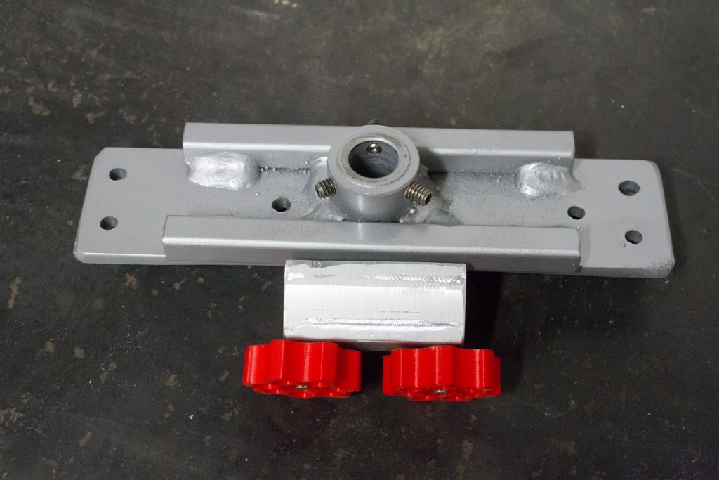
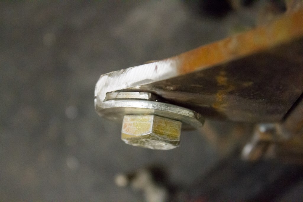
The countersunk 1/4″ screw secures the clamp to the declination shaft, and three set screws prevent wobble.
The clamp works better than I imagined. The knobs don’t need much of a hard turn to totally secure the scope. I had a couple nightmares about something unforseen happening and the scope sliding out of the clamp. A screw was added to the base plate to prevent the dovetail from sliding all the way out.
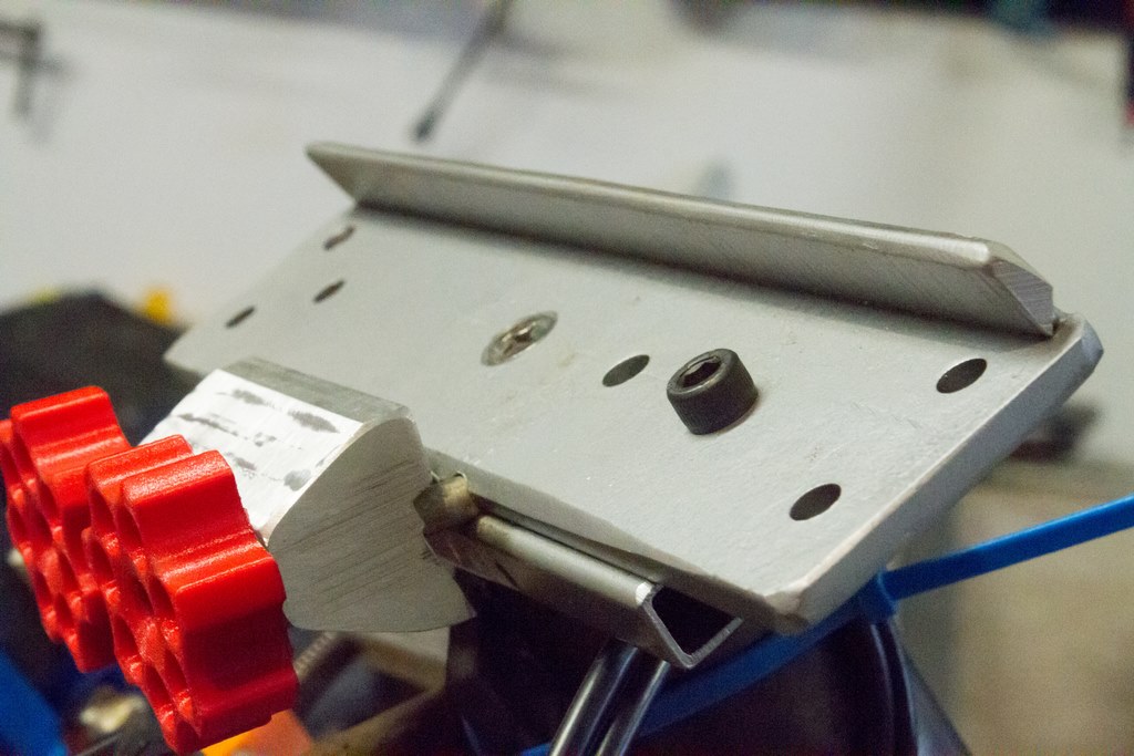
Right now there aren’t any stops on the screws, so the knobs will fall off if they’re backed too far.
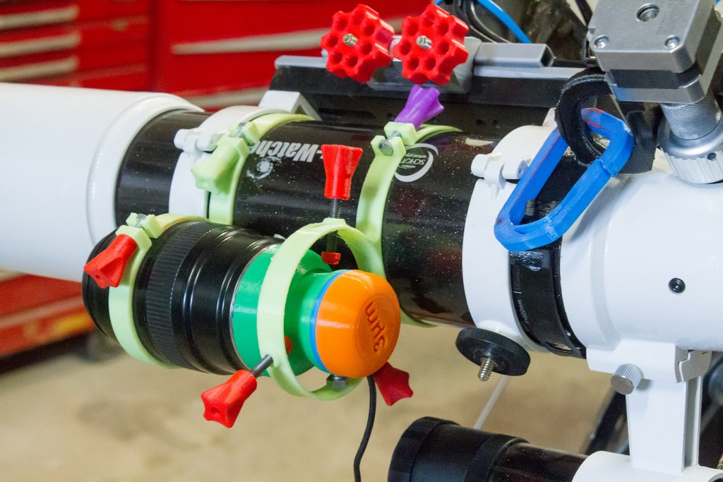
Focusing Motor
It’s handy to focus the scope without touching it, since any bumps can really shake the whole thing. Also, I can adjust the focus remotely (so if it’s cold outside, I’ll just do it inside).
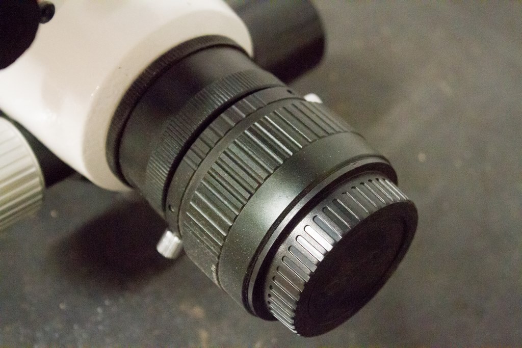
The scope came with a dual-speed 10:1 focuser. Unfortunately it did not have any allowance to let me install a focuser motor. So I removed the low-speed knob (and lost it…) then turned an aluminium replacement knob to replace it.

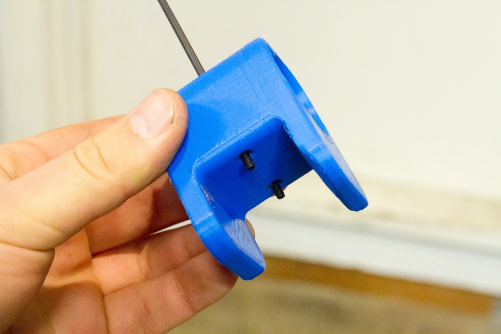
The knob uses M3 set screws to secure it onto the 2.4mm low-speed shaft of the focuser. The other side of the knob has a 5mm hole. I can insert a NEMA17 motor into the hole. The motor needed a mount to secure it on the scope. Here’s the 3D printed mount.
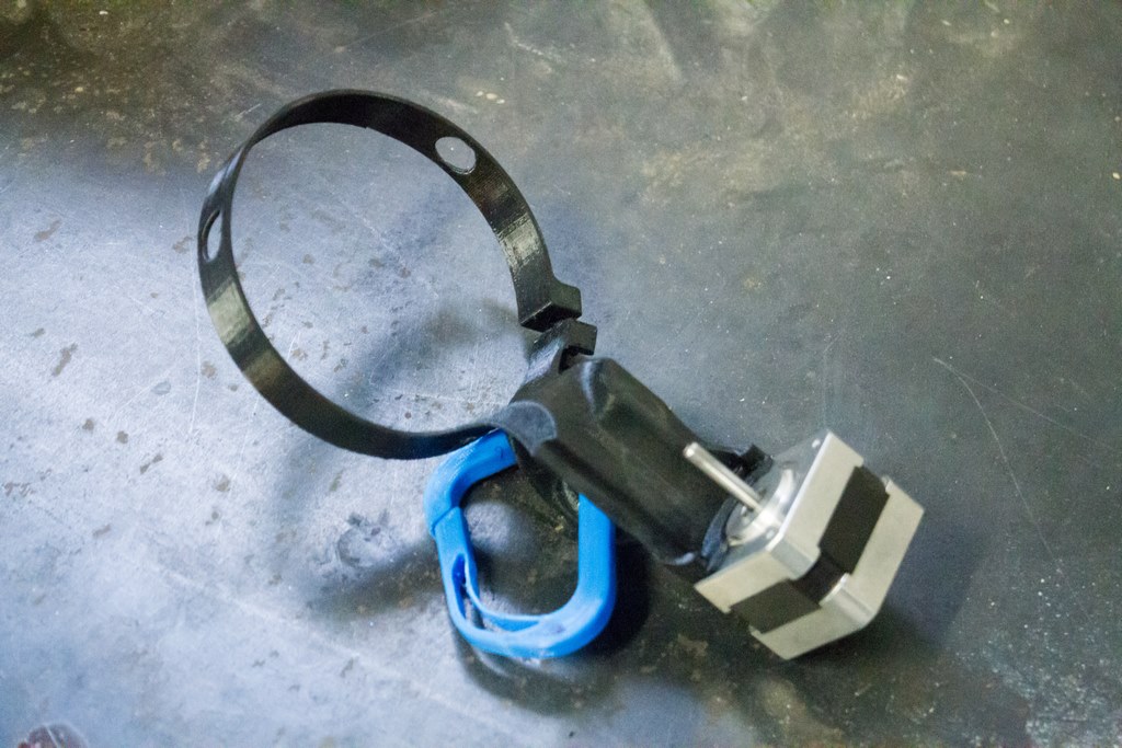
The PETG mount is flexible enough that I can just slide the motor shaft into the knob without separating the motor from the mount. An M5 screw (not shown) tightens the clamp around the telescope.
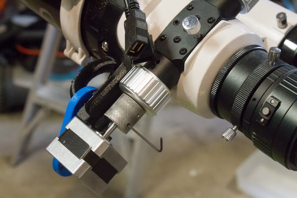
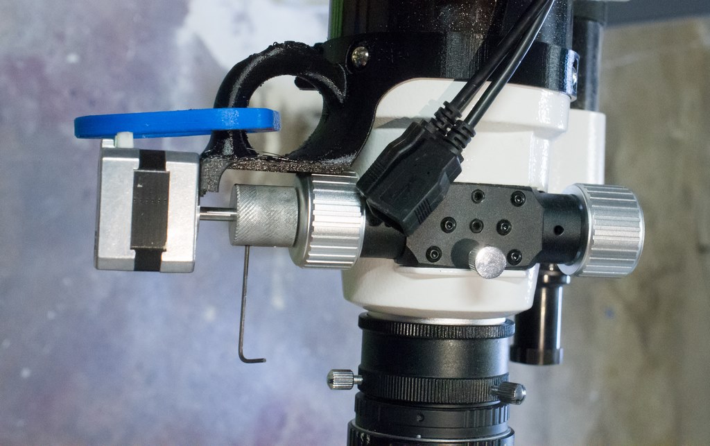
I expected to use the set screw to secure the motor shaft, but so far it seems that there’s just enough friction that the set screw does not need to be tightened. This is nice, since I would prefer not to carry the allen wrench with me to install the focuser motor.
Guide Camera
A guide camera is just a second camera on the mount which the computer can use to target a star and tell the mount to make small course corrections (hurry up westward, nudge north just a bit, etc). My PC runs PHD2 Guiding, which connects to the webcam and does all the work automatically.
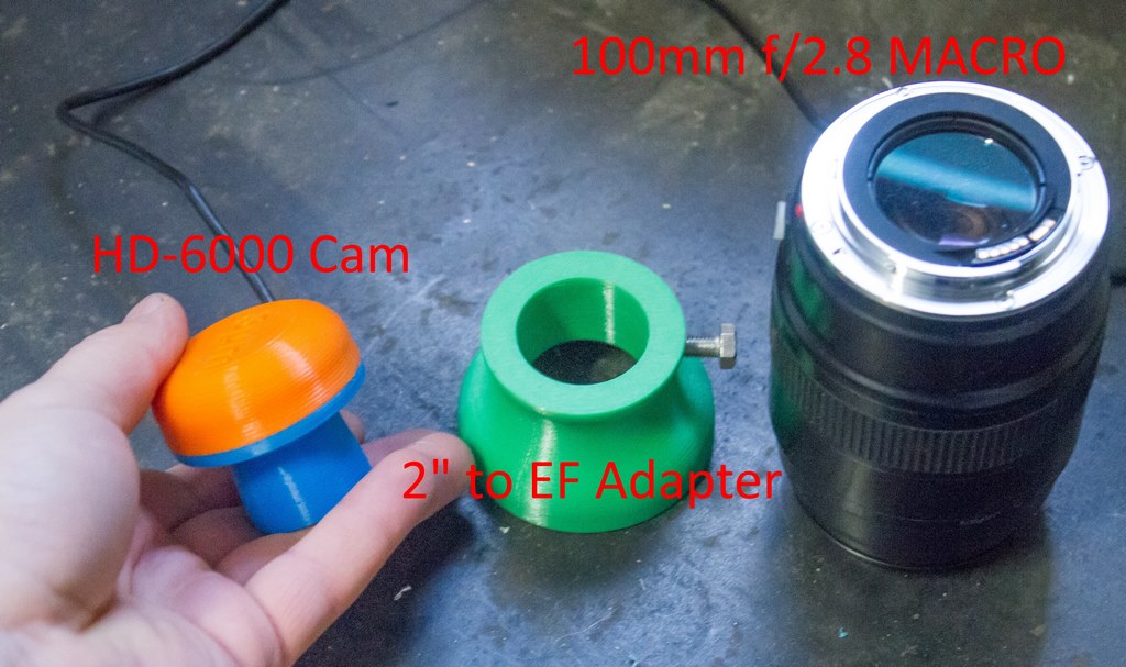
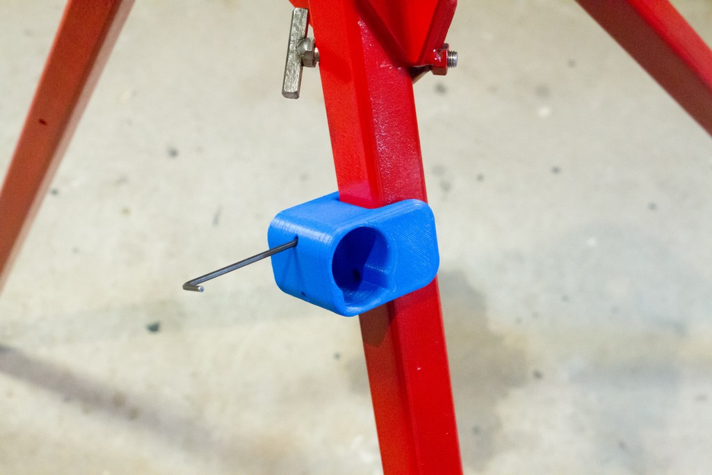
I hacked a Microsoft HD-6000 into a scope cam. Unfortunately I didn’t document the process, but you can find the STL files for 3D printing on here on Thingiverse. The conversion is very easy – dissasemble the HD-6000 (keeping the two sensor-mounting screws), install the sensor on the new housing, install the cover using M3 x 10mm screws.
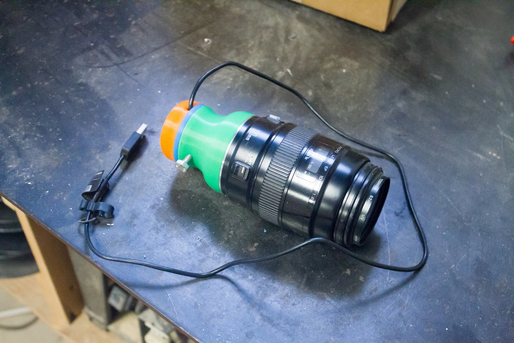
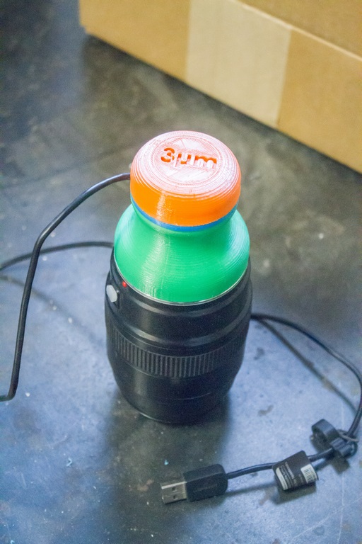
The green portion is simply an adapter to convert the camera’s 2″ mount to a Canon EF mount. I’ve been using my 100mm f/2.8L Macro for now, but would like to get another lens to use permanently (since I still like to use the lens for regular photography).
Here’s the sensor inside the housing. The UV/IR cut filter is gone, which usually means there will be some star bloating. I haven’t noticed any issues using it for guiding though.
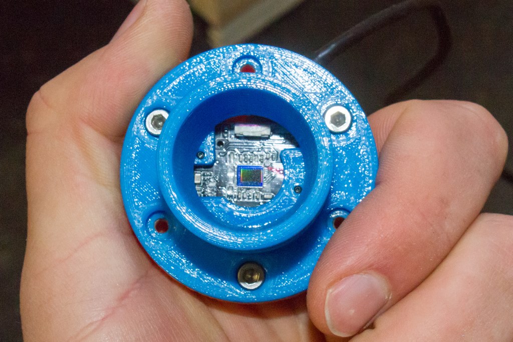
Unfortunately it seems that the plastic transmits a small amount of light, so the camera is sensitive to ambient lighting near the scope. I painted the interior of the camera housing to reduce light transmission and am looking forward to seeing if it made any difference.
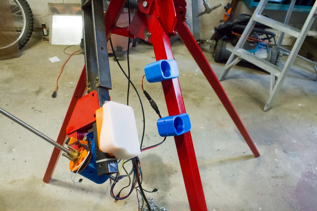
I’ve been mounting the scope with a set of 3D printed mounts.
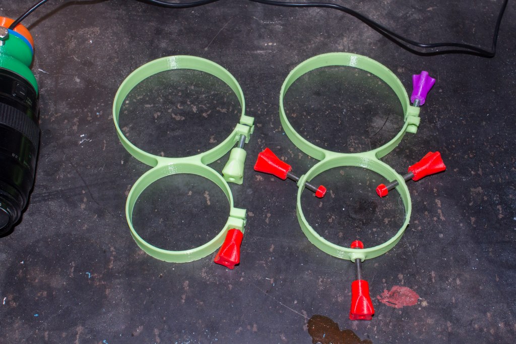
The mounts have worked to some degree, but I really don’t like them. Eventually they will be replaced, but here’s some photos anyways. The screws are all M5. I can aim the scope using the three red screws, but that really isn’t a fun activity. The mount flexes too much and the knobs don’t adjust well.

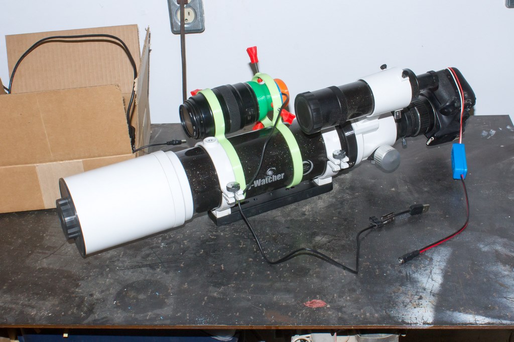
Power Supply
I use DeWalt 18V XRP tools in my garage, so I’ve developed an adapter to use the batteries in my projects (I call it the DeWatt). One battery can power my scope for several hours in the cold. I’ve recently started setting up a second battery adapter so that I can swap batteries without depowering the scope. This requires a couple diodes to prevent current from reversing into the drained battery, I have some 7A Schottky diodes.
The microcontroller blinks an LED to indicate battery voltage (4 blinks = Full, 1 = Empty, etc.). It would be nice if there was allowance in ASCOM for this data, then I could monitor it from a computer application. Oh well, I can go out and check the scope every now and then…
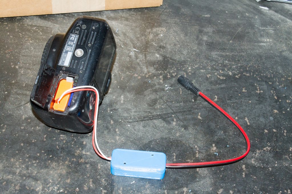
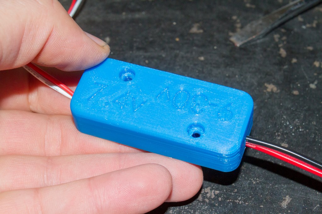
I use a Canon T5 for imaging. A 3D printed battery blank (found here on Thingiverse) is wired up to a switching power supply (set to 7.4V), which connects to the telescope power. I would share my own design for the switching supply housing, but it’s no better than the plethora of housings already available on Thingiverse.
Controller & ASCOM Driver
I use Astrophotography Toolkit (free to try a full-functional version, and affordable to purchase a license) and PHD2 Guiding (free!) during imaging. The problem with using two sets of software is that a standard ASCOM driver only allows one connection at a time – so APT and PHD2 can’t share the driver. To solve this, I wrote a Local Server driver (available here) – more details on the driver development in this blog post. The other benefit of using a local server driver is that the telescope controller can also run the focuser motor – no need for a second controller.
The driver and firmware are far from matured, but seem to be functional enough to be used.
The controller uses an ATMega328P microcontroller with an Arduino Uno bootloader. It doesn’t have a big workload, just three motors (two of which don’t move much), voltage monitoring, LED blinking, and serial communication with the driver. An Arduino would be just as good, but I prefer to build the entire controller on one PCB.
I will update this post as changes are made. Thanks for reading!
Last Updated 2019-09-17
HELLO
I am looking for help motorizing my GEM which holds a variety of telescopes I have made. The mount came from a Deep Space 16, so is heavy duty, and the equitorial axis has a large gear already. If you think you can help me, please contaact me at
bmarriott13@comcast.com Thank you for your time to read this
Bill marriott
SF Bay Area
415-827-7824