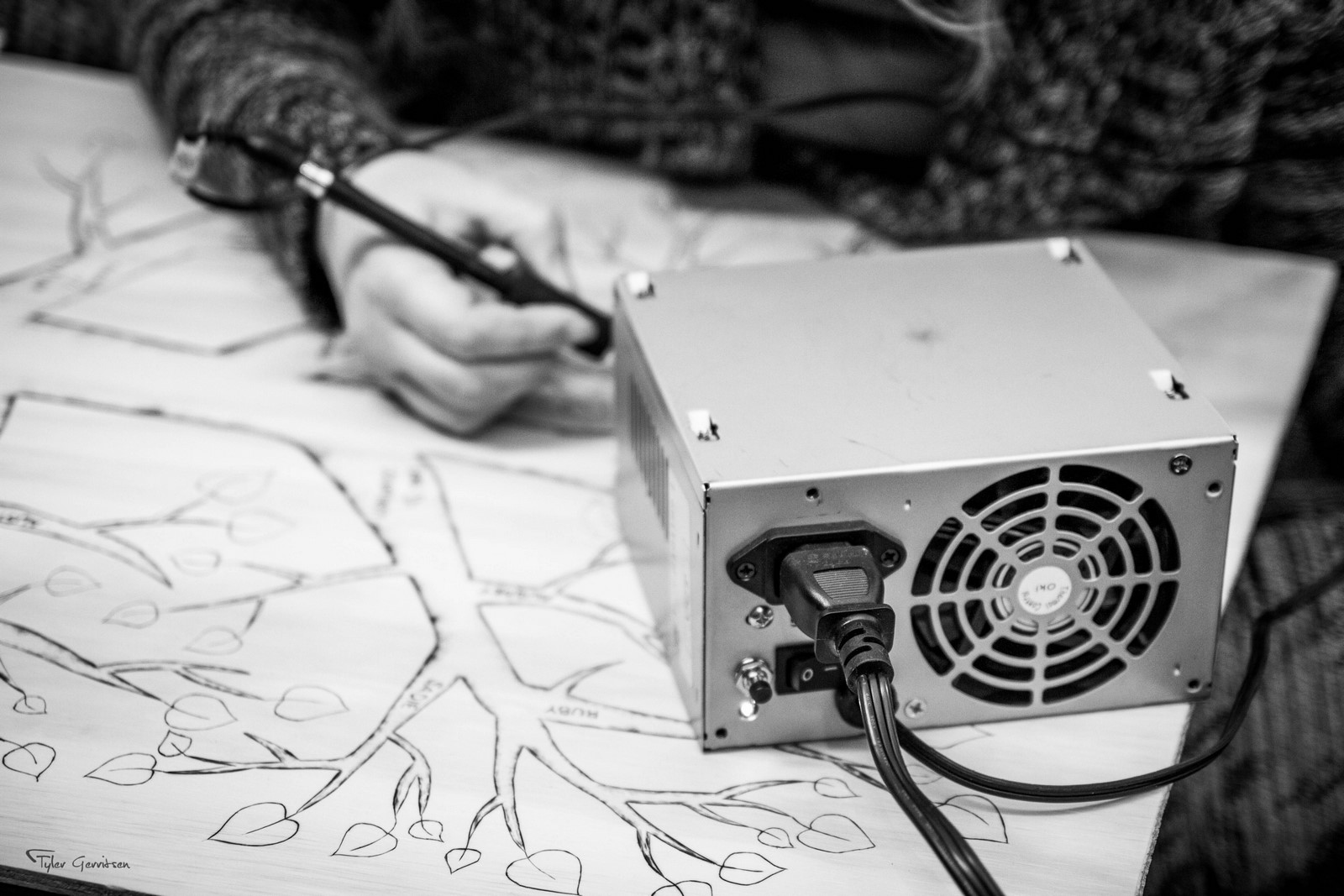
Woodburning, Not Money-Burning
Wood burning is a popular hobby which can become quite expensive. A quality wood burning system consists of: 1. A pen or selection of pens and 2. A power supply (station). I decided to invest in a series of Razertip wood burning pens simply because they were available at a local Lee Valley Tools store. They also have a 1-year unconditional warranty! If I end up destroying a pen with a home-built supply then we will find out just how unconditional the warranty is. The pens are available for ~$30 each, which can become a significant investment if you want more than one or two. The stations run for $165 and up, which is the same price as six pens! So lets ditch the station.
The Power Supply
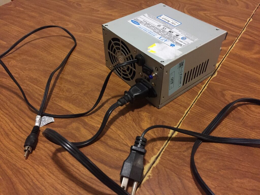
According to this fantastic pyrography resource, the Razertip station provides 2 volts and the pens draw 10 amps. It isn’t clear if the regular or heavy duty pens draw this much current. I suspect that it is the heavy duty pens since they require a special cord rated for 10 amps. So what can provide 2 volts at 10 amps? An ATX PSU with a PWM-controlled output!
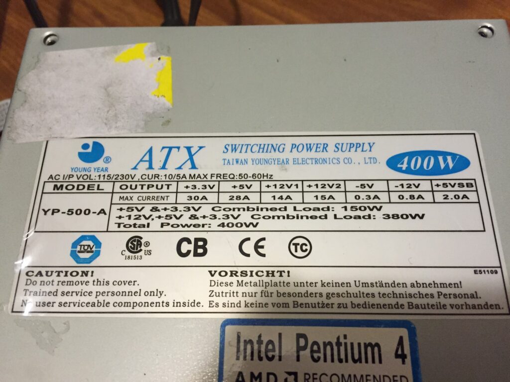
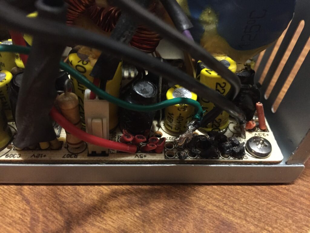
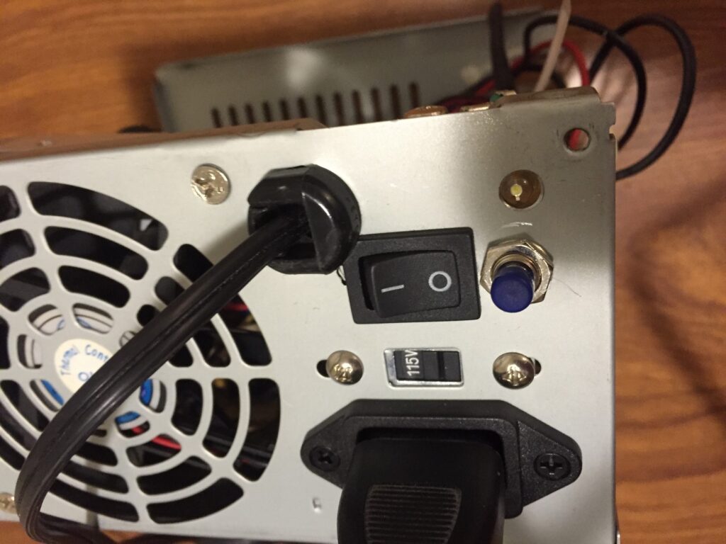
An ATX PSU requires a small amount of modification to be useful for other projects. This article explains the right way to do it. I skipped a few steps, simply cut all wires except for a ground (black), +3.3V (orange), and +5V (red). I also connected the green wire directly to ground so the PSU will turn on as soon as the main power switch on the back (now the front!) is turned on.
The PSU’s 3.3 volt rail was rated for 30 amps. The idea was to control the 3.3 volt output with a MOSFET. This provides the correct power output without damaging the PSU. I selected a MOSFET with a low gate capacitance so that an ATTINY85 microcontroller could drive the gate at high frequency. Mistake! After hooking up the 3.3V output to a pen and driving the IRL540N’s gate without any resistors, an oscilloscope revealed significant voltage spikes (>40V) when the transistor was energized and de-energized.
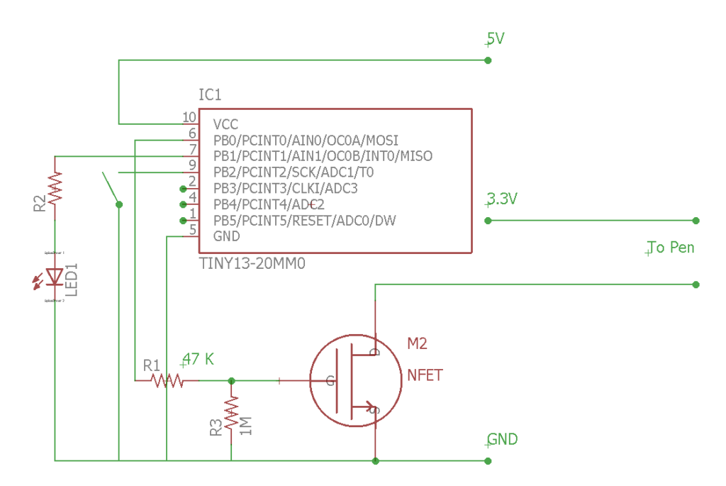
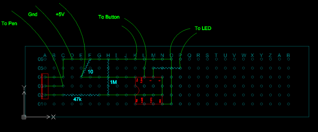
So, I kept using the same transistor but added a 47K ohm resistor between the microcontroller and the transistor’s gate. A few resistors were experimented with first. A 47K ohm was the lowest to completely eliminate the voltage spikes. The slow state change resulted in a significant amount of heat from the transistor, so I found a suitable heatsink from another junked electronic board and mounted the transistor on it. The transistor and controller were mounted inside the PSU with the heatsink adjacent to the fan. Just to be sure that the brutality to the PSU was minimized, the PWM frequency was kept very low. Driving the transistor at about 50 hertz did not seem to affect the pen’s performance. I haven’t experimented with even lower frequencies to see how low it could go.
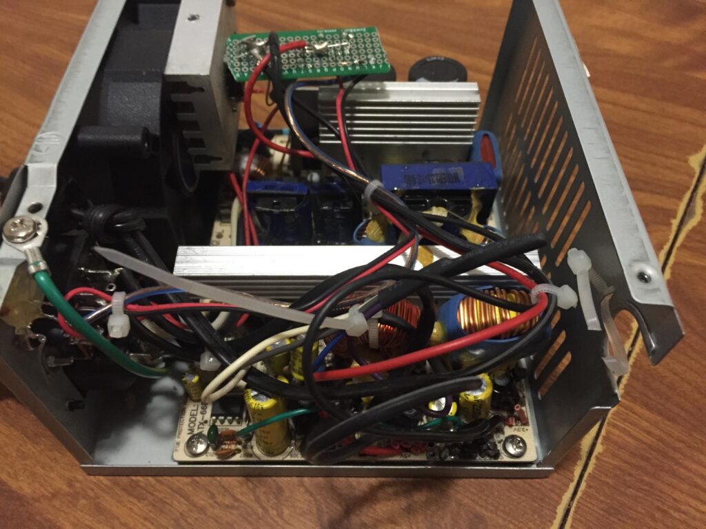
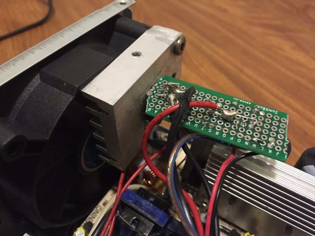
The heat output was controlled by pressing a button mounted on the PSU case beside the power switch. It has five settings, which can be re-programmed after the unit has been field tested. An LED indicates the station’s status. The logic portion of the unit is powered by the PSU’s 5V rail (so that it’s separated from any power irregularities on the 3.3V rail). The 5V rail also has a low-resistance, high-power dummy resistor to keep the switching power supply stable.
As for a cable, the pens connect to the station via a basic RCA connector. I happened to have an RCA cable handy, so I simply cut one end off and connected it to the station. About 2 feet of cord is sufficient, and can be extended if there are any complaints.
Firmware:
Here’s the Arduino Sketch.
//Written by Tyler Gerritsen
//2017-10-21

//Version 1.1 (Release 2018-02-19)
//Much cleaner code
//LED heartbeat function

//Pyrography Pen Power Supply Controller
//Written for ATTiny85 w/ Internal 1MHZ Clock

//One short button press = increment PWM output
//One long button press = turn off output


//Set your ATTiny85 Pinout Here
#define BUTTON_PIN 2
#define LED_PIN 1               //Needs to be PWM
#define POWER_OUTPUT_PIN 0

//Set your Button settings here
#define BUTTON_DEBOUNCE 400       //Debounce time
#define BUTTON_LONGHOLD 1500      //Time to hold for secondary button function

//Set your PWM settings here
#define OFF_TIME_MICROSECONDS 5000                            //Single value time off duration
#define ON_TIME_MICROSECONDS {6800, 6300, 5800, 5300, 4800}   //Array of time on durations - list size may be increased
#define ON_TIME_OPTION_COUNT 5                                //Number of values in above array


//Global Vars
const byte btnPin = BUTTON_PIN;
const byte ledPin = LED_PIN;
const byte pwrPin = POWER_OUTPUT_PIN;
byte powerLevel = 0;


void setup() {
  pinMode(btnPin, INPUT_PULLUP);
  digitalWrite(btnPin, HIGH);
  pinMode(ledPin, OUTPUT);
  pinMode(pwrPin, OUTPUT);
  digitalWrite(pwrPin, LOW);
  analogWrite(ledPin, 0);
}


void loop() {
  runBurner();
  checkButton();
  blinkLED(-1);
}


void runBurner(){
  static unsigned long _nextChange;
  static boolean _onOff;
  static const unsigned int _onDelay[ON_TIME_OPTION_COUNT] = ON_TIME_MICROSECONDS;

  if (powerLevel){                        //Burner is on
    if (micros() > _nextChange){          //Timer is up - Toggle pin on/off
      if (_onOff){
        digitalWrite(pwrPin, LOW);
        _onOff = false;
        _nextChange += _onDelay[powerLevel];
      }
      else {
        digitalWrite(pwrPin, HIGH);
        _onOff = true;
        _nextChange += OFF_TIME_MICROSECONDS;
      }
    }
  }
  else if (digitalRead(pwrPin)) digitalWrite(pwrPin, 0);  //Burner is off
}


void blinkLED(int8_t blinks){
  static byte _blinks = 0;
  static unsigned long _nextEvent = 0;
  static const byte sineWave[32] = {0, 3, 10, 22, 38, 57, 79, 103, 127, 152, 176, 198, 217, 233, 245, 252, 254, 252, 245, 233, 217, 198, 176, 152, 128,103, 79, 57, 38, 22, 10, 3};
  static byte _sineWavePosition;
  static byte _ledOn;

  if (blinks > -1) {             //Start blinking
    digitalWrite(ledPin, LOW);
    _nextEvent = millis() + 600;
    _blinks = blinks;
    _sineWavePosition = 0;
  }

  else if (millis() > _nextEvent){    //This is the timer, it controls the blink speed and the heartbeat speeed
    if (_blinks){                     //Toggle LED on/off after timer is  up
      if (_ledOn){
        _ledOn = 0;
        digitalWrite(ledPin, LOW);
        _blinks--;
        _nextEvent += 150;
        if (!_blinks) _nextEvent += 600;
      }
      else {
        _ledOn = 1;
        analogWrite(ledPin, 10);
        _nextEvent += 150;
      }
    }
    else {                    //Heartbeat
      _sineWavePosition++;
      _sineWavePosition %= 32;
      analogWrite(ledPin, max((sineWave[_sineWavePosition] / 10),1));
      _nextEvent = millis() + 50;
    }
  }
}


void checkButton(){
  byte _b = readBtn();  //Read the button (0 = no press, 1 = short press, 2 = long press)

  switch (_b){
    case 1:
      powerLevel++;
      powerLevel %= (ON_TIME_OPTION_COUNT + 1);
      blinkLED(powerLevel);
    break;
    case 2:
      powerLevel = 0;
      blinkLED(0);
    break;
  }
}


uint8_t readBtn(){  //Return 1 if short pressed & released, Return 2 if long pressed PRIOR to release
  static unsigned long debounceTimer;
  static unsigned int buttonRead;
  static byte buttonPos;

  buttonRead = 1 - digitalRead(btnPin);     //Pin is pulled up

  if (buttonRead && millis() > debounceTimer){   //Button depressed
    if (!buttonPos){
      buttonPos = 1;
      debounceTimer = millis() + BUTTON_LONGHOLD;
    }
    else if (buttonPos == 1){
      buttonPos = 2;
      return 2;
    }
  }
  else if (buttonPos && !buttonRead) {
    debounceTimer = millis() + BUTTON_DEBOUNCE;
    if (buttonPos == 1) {
      buttonPos = 0;
      return 1;
    }
    buttonPos = 0;
  }
  return 0;
}