Another Microsecond Flash?
Yup, I’ve been working on a new design for about one year now. Here it is!
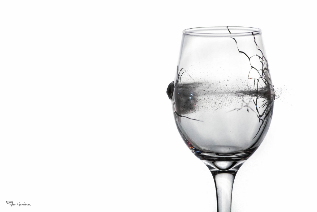
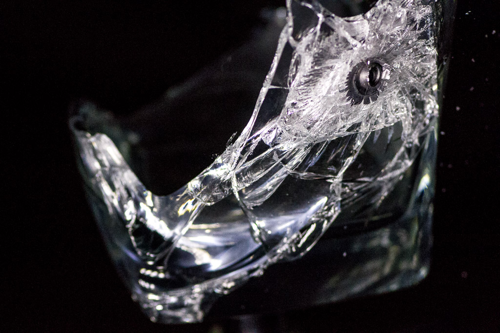
My first high-speed LED strobe design was the Edgerton. The goal was to build a strobe that could be used to photograph supersonic bullets for as little $$$ as possible. It was functional and I was very pleased with the result!
Shortly after finishing the design, I came up with a wishlist for a second version (originally called the MK2, I’ve now designated it the E2 Series):
- DFM (Design For Manufacturing)
- 4x AA batteries instead of 8x
- Improved design factor for extended life
- Better user interface
E2 Series Strobe
The E2-A is the first submodel of the E2 Series. It is designed exclusively for microsecond strobes used for high-speed photography. I have plans for two more submodels:
- All three will use a common set of core components and firmware
- A high-power unit will be tuned for higher exposure at shorter durations. I hope to increase the light output by about 2x, but the result is yet to be seen.
- A videography submodel will have the same functionality as the E2-A, but will also be equipped with a constant illumination mode to produce around 100 – 200 watts of light. That’s alot of light!
The E2-A uses the same LED as the Edgerton. Why? I have a large amount of experience with the CREE CXA2530 in high-powered strobing. The total test illumination is approaching one full second! To use a different LED would require significant testing to determine the limitations of the LED. To add to that, LED technology hasn’t really changed that much in one year! The CXA2530 (and its brother, the CXA1830) are still the best bang-for-buck LED in their class.
Can I Build or Buy It?
Yes and yes! The new E2 uses more complicated manufacturing processes and fewer off-the-shelf parts than the original Edgerton. I’ve made all documentation and design files available (under an open-source license) including the assembly manual.
IMPORTANT NOTE #1: This strobe pushes the capabilities of the LED’s. Complete failure of the LED’s is possible. That means the expensive components can be accidentally destroyed and require replacing. I’ve taken many precautions in the design to prevent this, but please consider building a strobe at your own risk.
IMPORTANT NOTE #2: The LED’s are not as powerful as a Xenon flashtube, and they do not turn on as long as a typical camera strobe. Expect to crank up the ISO by several (4 or more) stops in order to capture usable images.
If you want a strobe, you have three options:
- If you want to build the whole strobe by yourself then have fun, be safe, and send me any questions or a photo if you like!
- If you’re interested in purchasing a complete unit, please email me at tyler@td0g.ca for pricing and lead time.
- If you would like to build one, but cannot build the faceplate or electronic control boards, I am happy to sell those parts. Please email me at tyler@td0g.ca and let me know what you need.
Not sure if you have the skills or equipment to build it? Here’s a checklist to help you decide:
- Can you manage to stay safe around high-voltage electronics? We aren’t talking about spark-gap voltages, but 120 volts will still hurt!
- Can you solder surface-mount electronic components?
- Do you have a 3D printer with 200mm x 200mm heated bed?
- Do you have access to a mill & drill press for the aluminium faceplate?
If you answered YES to all of these questions then you will be able to build the flash! If you answered yes to SOME of the questions, then consider buying the more difficult components and assembling the rest yourself.
So What’s New?
The original design was a starting point for the E2-A. When I designed the Edgerton, I relied heavily on destructive testing of the LED’s to make design choices. In designing the E2-A, I spent a significant amount of time reviewing the design and testing every part of the circuit. That testing has led to a number of changes which improves the design factor and increase the expected life of the LED’s.
NOTE: I have thousands of scope traces and a large amount of notes that I am currently working on organizing and uploading to the repository.
So what did I change? Here’s a list of highlights:
- Regulating the gate driver voltage allows for lower battery voltages and more control over the strobing power
- Improvements to the parallel gate circuits to prevent ringing and overshoot while maintaining a fast rise/fall time
- Selection of a new MOSFET (multiple MOSFET’s and IGBT’s were tested to identify the most important characteristics of the transistor)
- Adding an RC snubber circuit in parallel with the MOSFET’s drain and source
- A MIC3172-based capacitor charger to replace the eBay-sourced ZVS charger
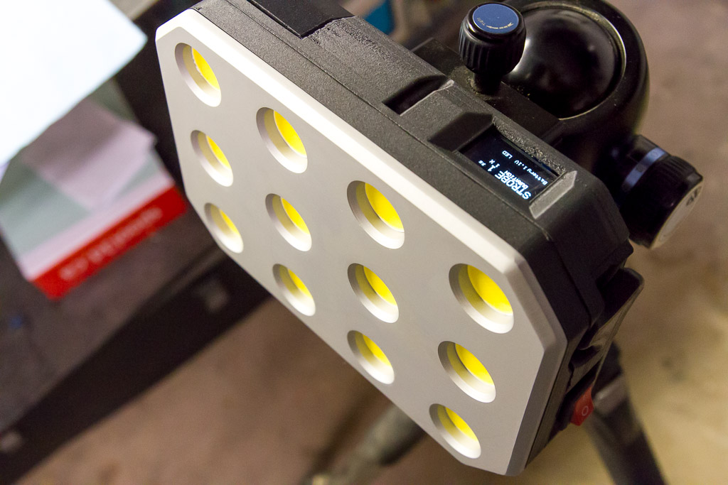
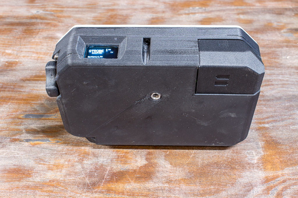
- An OLED display to replace the old 7-segment display
Additionally, I’ve also added allowances for constant-illumination modes!
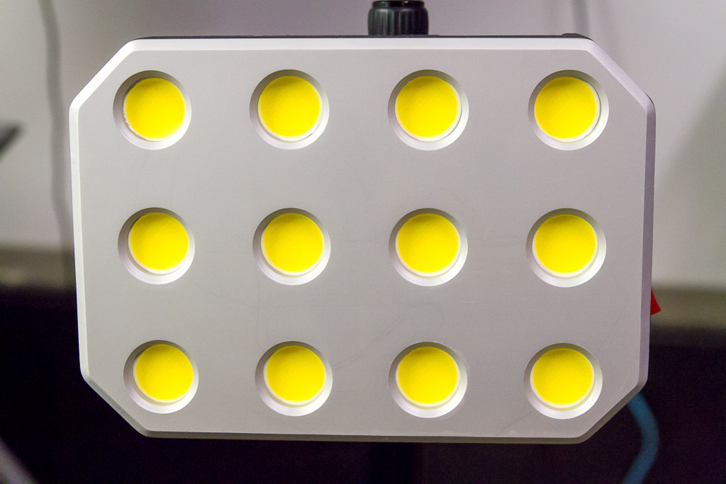
- The faceplate is now made from aluminium to allow significant heat dissapation
- The high-pass protection filter can be equipped with an optional ‘disable’ circuit to allow continuous-on mode (instead of the ~4.5 microsecond max ON time)
- The new control board (EMCB1) is not only capable of operating three power controllers, a temperature sensor, the UI and triggering system, but it is also backward-compatible and can be used in the original Edgerton strobe (in place of the EMCB0)
On top of all that, I’ve also made improvements that can trickle down to the original Edgerton:
- The 4x AA battery mod can be applied to the Edgerton design (and is recommended for its improved voltage regulation!)
- Multi-strobing!
On The Outside
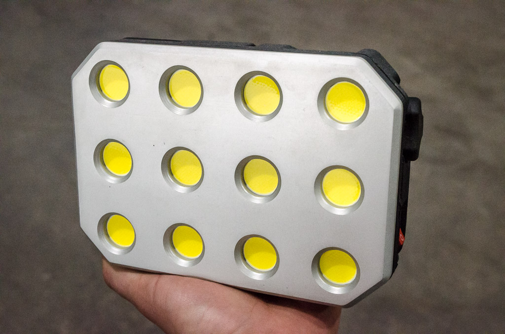
The new faceplate is made from anodized aluminum. The decision to use aluminum was primarily because of my plans to have a constant light source mode (which hasn’t been fully implemented yet…) and the aluminum is perfect to cool the LED’s passively. Additionally, the aluminum looks great and gives the strobe a nice asthetic. I’m constantly tempted to invest in a laser so that I can etch a fancy logo into the anodized surface.
I had fun learning how to anodize the aluminum. That’s a topic for another forum post, but I do need to say thanks to the folks on the caswellplating forum and especially Janger on the canadianmetalworking forum. Many mistakes were made, but thankfully it is easy to make several attempts on one piece! The final product came out looking quite nice. Now I’m salivating over some nice lasers which could etch a logo into the faceplate!
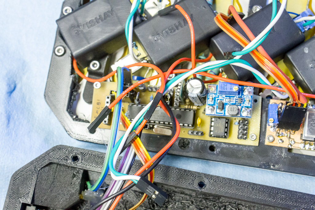
The unfortunate bit about the aluminum is that it conducts electricity slightly better than the PETG used on the original design. I had to take that into account and design ways to prevent the conductors from contacting the aluminum. First, the faceplate has 3mm deep recesses for the electronics and the recesses are coated with polyurethane.
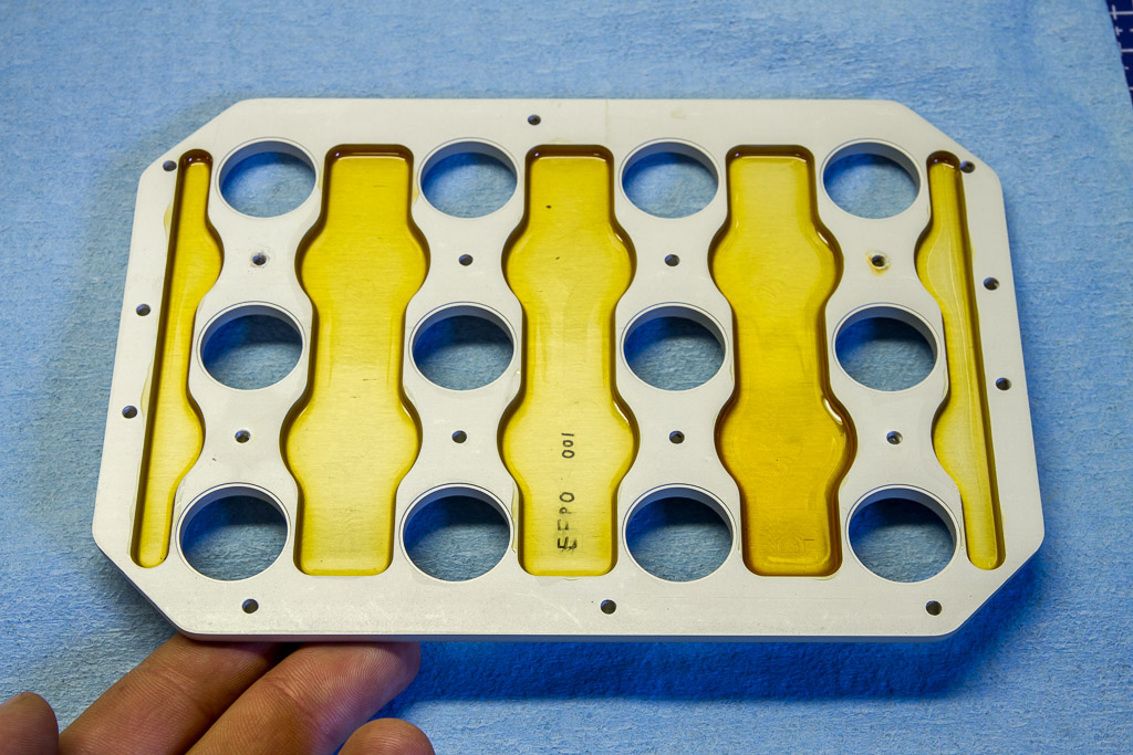
Second, the resistors are carefully routed so that the leads are not near the aluminum. Finally, the bared wires are secured with zip-ties.
OLED Displays Are Awesome!
The original flash had a very affordable display (probably the nicest thing to say about the 7-segment display). This time around I wanted the display to be intuitive, able to handle many features, and look snazzy. So it obviously had to be an OLED!
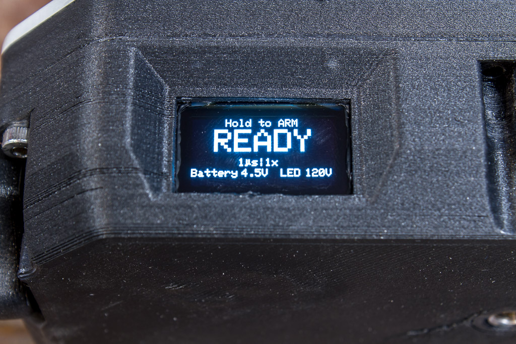
The 128 x 64 resolution is the perfect size to display all of the settings (discussed below) without confusing the operator. These displays seem to come at any price that you would like to pay, so I opted for the more affordable models from Amazon.
Half The Batteries, Four Times The Fun (inverse-square law)
The new design only uses four batteries. That is made possible because of the new power supply architecture. All power rails in the unit are now regulated, unlike the original design’s unregulated gate driver voltage. Also, the 5V rail is supplied by a switching buck/boost supply, instead of the original LM7805 linear regulator.
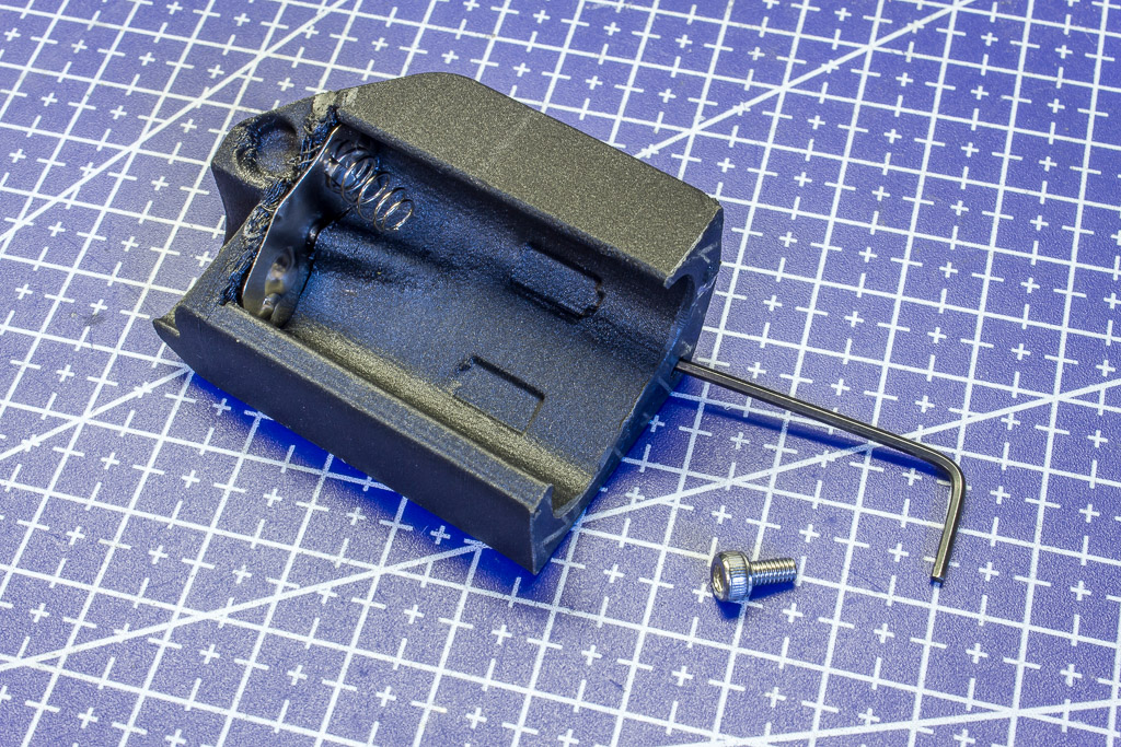
I took some inspiration from my Xbox360 controller and made a battery cover that also carries two batteries (the other two are inserted directly into the strobe). I 3D printed no less than 7 different prototype battery covers during the iterative design process. The batteries slide smoothly and stay in the cover while it is removed, while at the same time the cover can be inserted onto the strobe with a satisfying ‘click’.
Capacitor Charger
In designing the new strobe, I had to decide which power supplies to use ‘off-the-shelf’ and which to build from scratch. I searched for a suitable capacitor charger, but none were to be found with the feature set I wanted:
- 3V – 6V input
- Adjustable up to 200V output
- ‘Enable’ signal (so the microcontroller can turn it on and off directly, no relay required)
- $20 CAD or less
- Small enough to fit beside the capacitors inside the case
I found one that came close – a cap charger from eBay which had the markings sanded off! It met all of my requirements except that it did not have an enable signal (it was always on). So, I did some sleuthing (thank you Digikey for your search and filtering tools) and figured out that the IC was a Microchip MIC2171, which happens to have a brother – the MIC3172 – which has an enable pin!
Thus the ECC0 capacitor charger was born. I can’t take all the credit – Micrel has an application note explaining how to use the MIC3172 as a capacitor charger for a photography strobe. It charges the capacitors to 120V in under 2 seconds and uses very little power (less than 200mA) to maintain the capacitor voltage. The large flyback transformer is a Coilcraft DA2032 which, although larger than I had hoped, has some nice characteristics that makes it work will with the MIC3172.
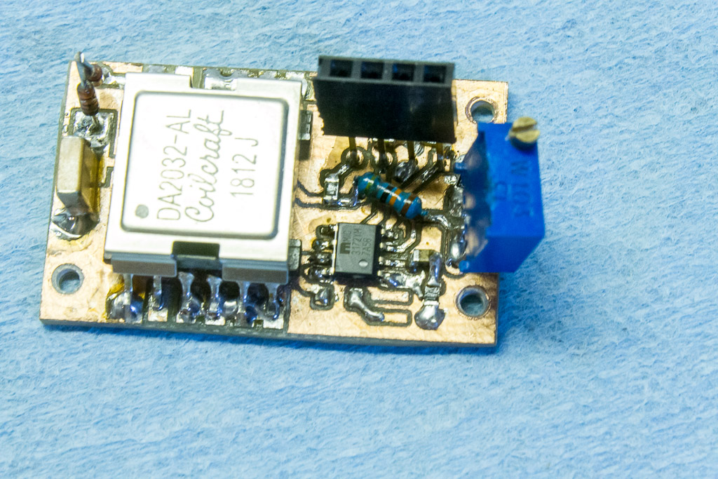
I’ve manufactured a couple ECC0 capacitor chargers and have just placed an order for PCBs so that several more can be manufactured. The design files are available on Github.
Power Supplies
Two more power supplies were required: a 5V buck/boost converter for the control board and display, and a 10 – 20V adjustable boost converter for the MOSFET Gate Driver. I found some good options available and opted to use those components.
The 5V buck/boost converter is a Pololu S7V7F5 5V Step-Up/Step-Down Voltage Regulator. It’s tiny, accepts voltages as low as 2.7V, and can output at least 500mA. Perfect!
The gate driver boost converter is an SX1308-based board. These things are cheap and have good stability with varying input voltages. I had originally designed it to recieve voltage from the 5V rail, but after some testing it turns out that the SX1308 works great on battery voltages from 2.5V to 6V. I ultimately set the output voltage to 12.8V, and saved some space by removing the multi-turn pot and replacing it with 0805 SMD resistors.
LED’s & Transistors
The most valuable yet unseen parts of the new design is the new transistors and their gate filters. I really didn’t understand the inner workings of the IPP60R190P6 MOSFET transistors used in the original design until recently. Many hundreds of oscilloscope traces later, it became clear that those transistors were both remarkable and bottlenecking.
The datasheet indicated that the maximum pulse drain current was 57A. ‘Probably not really accurate’ I told myself, since the strobe was only turning the transistors on for a couple microseconds. Well it turns out that they were right! 57A was only possible if the gates had a fairly high voltage.
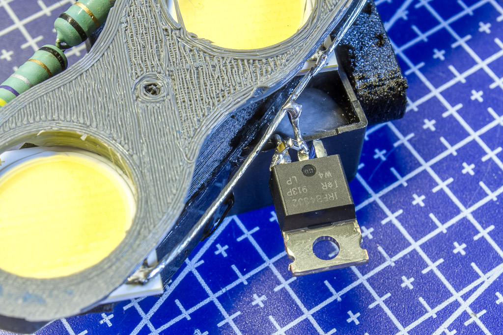
I didn’t want the transistors to limit the LED current since the gate voltage did not rise and fall in a perfectly orderly manner. So I began searching for a more suited transistor. I did not discreminate against other transistor flavours – IGBT’s were also interviewed. Alas, I ultimately settled on another MOSFET from Infineon – the IRFB4332.
The new transistor had a significantly higher gate charge, which meant that I had to modify the gate filter. Many dozen designs were tested, some of which included inductor coils, diodes, capacitors, resistors, and ferrite beads. The final design was remarkably simple and not too dissimilar from the original gate filter design. Even the ferrite bead selected from several options turned out to be the same ferrite bead used in the original design!
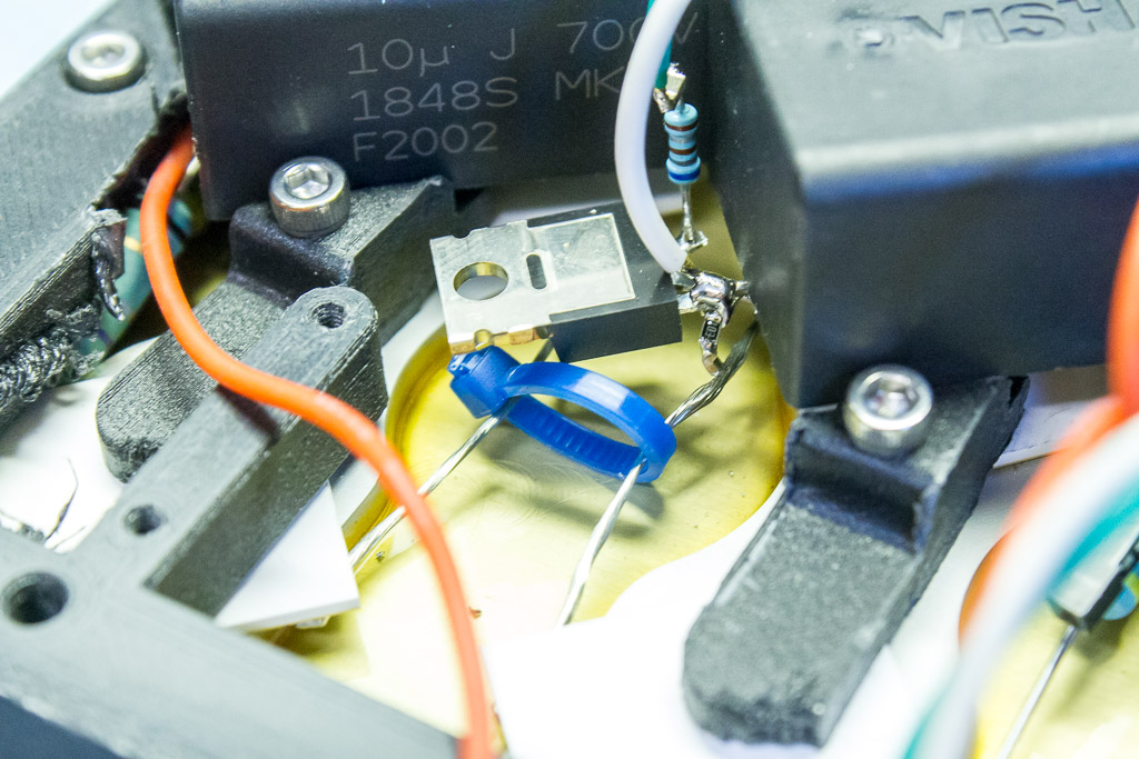
I also used the opportunity to install an RC snubber filter between the source and drain pins of the transistor. This has the effect of slowing the dV/dt rate and arresting any voltage spikes caused by gate voltage oscillations (darn the ringing!) Can you see the tiny 0805 resistor and capacitor?
Multi-Strobing
Also new to the E2-A is a multi-strobing feature. The strobe, when triggered, can fire up to six sequential strobes. The strobes can be from 250 microseconds to 2,000 microseconds apart.
The number of strobes, time between strobes, and strobe duration do have some limitations and not all combinations are possible (eg. 6 consecutive 4-microsecond strobes are not allowed). This is because my testing, which has been very encouraging, is also limited in the area of multi-strobes. I need to destructively test several more LED’s before I’m comfortable relaxing the limits and risking an array of 12 LED’s.
Other Improvements
I just want to point out a couple interesting discoveries that not only affect the E2-A, but also the original Edgerton.
I was unaware of this until recently, but it turns out that the bootloader I had used in the original design has a quirk. On booting, GPIO13 will toggle for about 1 millisecond. That pin is never to be used for mission-critical functions like controlling the high-voltage converter or gate driver!!!
In testing the original Edgerton, I noticed that about 1 in every 1,000 strobes would appear brighter. This did not make sense to me and I thought there was an issue with the MOSFET’s staying on longer than the gate voltage told them to. In testing the new E2-A, I had a full-on AH-HA moment and realized that this was caused by an interrupt firing in the microcontroller while the flash was turned on! This happens very rarely, but there can be unfortunate side effects if it does occur. I suspect it was the Arduino core’s millis() or micros() function updating. This is corrected by a global interrupt disable before firing the flash.
Prototype COB Reflector
LED’s have an unfortunately wide beam, which isn’t ideal for this application. I’ve spec’d out and priced COB reflectors, but they cost more than the LED’s!
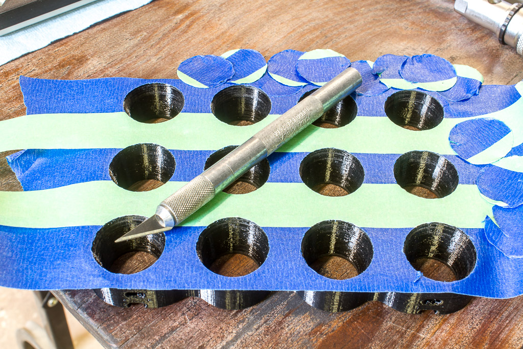
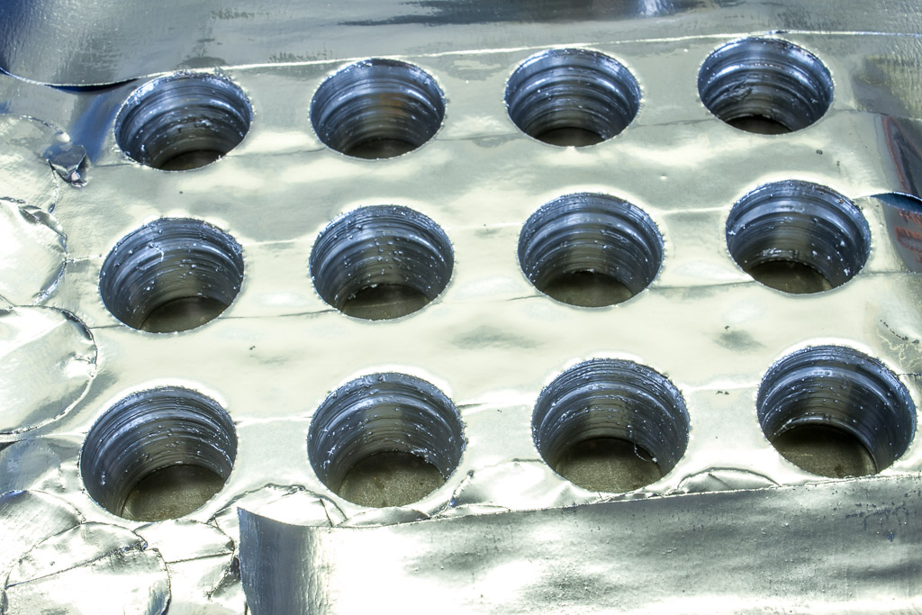
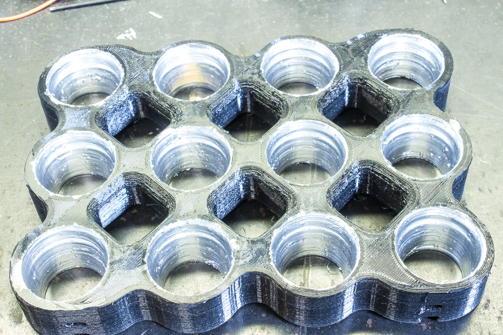
It recently struck me that I could try 3D printing the reflectors. Of course a highly reflective paint would be required, so I went to a big-box hardware store and bought a few cans of paint that might work.
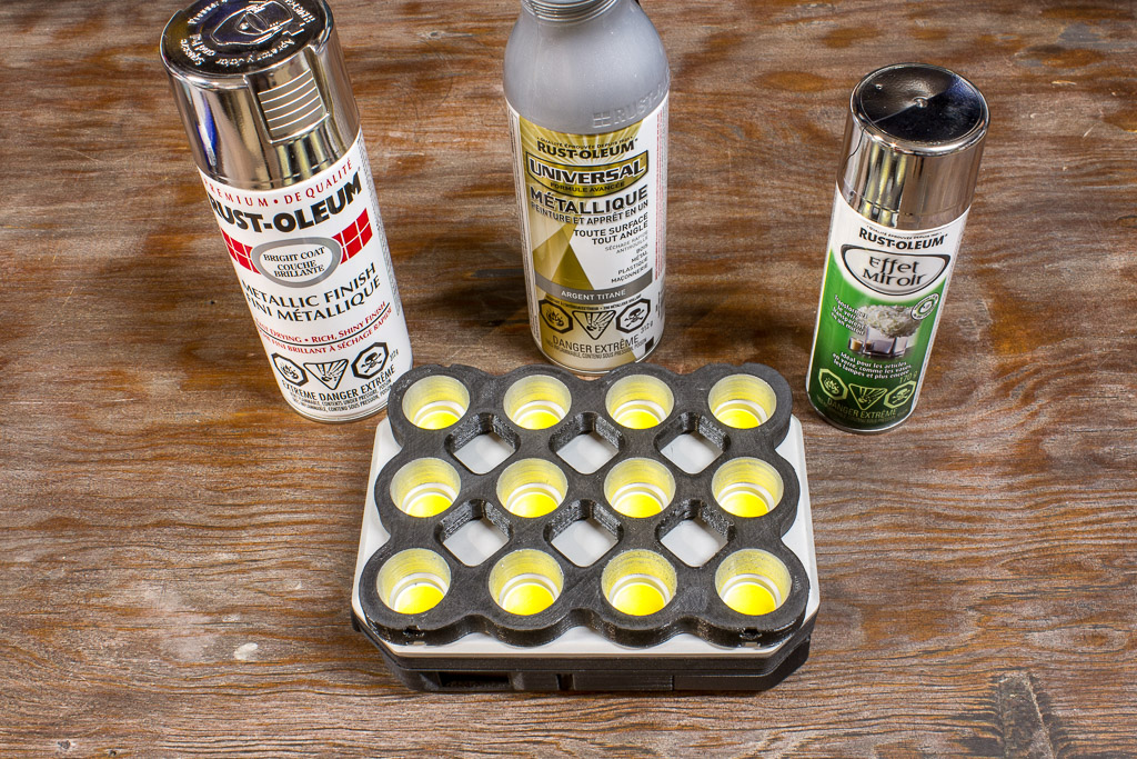
The winner was the Premium Rust-Oleum Metallic Finish (on the left). It was significantly more mirror-like than the other two. Above is a photo of the first prototype reflector, which worked surprisingly well given how little effort went into the design. The photo comparison below may not look significantly different, but even a 1/3 stop more light is worthwhile.

Painting the reflectors required lots of paint. Shown below is my process – mask, paint, done.
I am working on a proper design for the reflectors, but that’s just another project that I haven’t had enough time for yet. There are COB reflector design suites available, but my budget has been depleted for now. I have also ordered tooling so that I can post-process the reflectors with a CNC mill. A ball-nose mill bit should be able to smooth out the reflector surface nicely!
Repository
I’m continuing to keep everything in the same repository as the original Edgerton high-speed flash: https://github.com/td0g/high_speed_flash/tree/master/MK2/E2-A
License

All documentation for this project is licensed under a Creative Commons Attribution 4.0 International License.
The firmware for the E2 series strobe is licensed under a GNU GPL V3.0 license.
Thanks for reading!
Last updated 2020-07-03
Hello,
This looks like an amazing system – do you sell these units?
Best wishes
Alf