Pyrography Power Supply #DIY

Woodburning, Not Money-Burning

Wood burning is a popular hobby which can become quite expensive.  A quality wood burning system consists of: 1. A pen or selection of pens and 2. A power supply (station).  I decided to invest in a series of Razertip wood burning pens simply because they were available at a local Lee Valley Tools store. They also have a 1-year unconditional warranty!  If I end up destroying a pen with a home-built supply then we will find out just how unconditional the warranty is.  The pens are available for ~$30 each, which can become a significant investment if you want more than one or two.  The stations run for $165 and up, which is the same price as six pens!  So lets ditch the station.

The Power Supply

According to this fantastic pyrography resource, the Razertip station provides 2 volts and the pens draw 10 amps.  It isn’t clear if the regular or heavy duty pens draw this much current.  I suspect that it is the heavy duty pens since they require a special cord rated for 10 amps.  So what can provide 2 volts at 10 amps?  An ATX PSU with a PWM-controlled output!
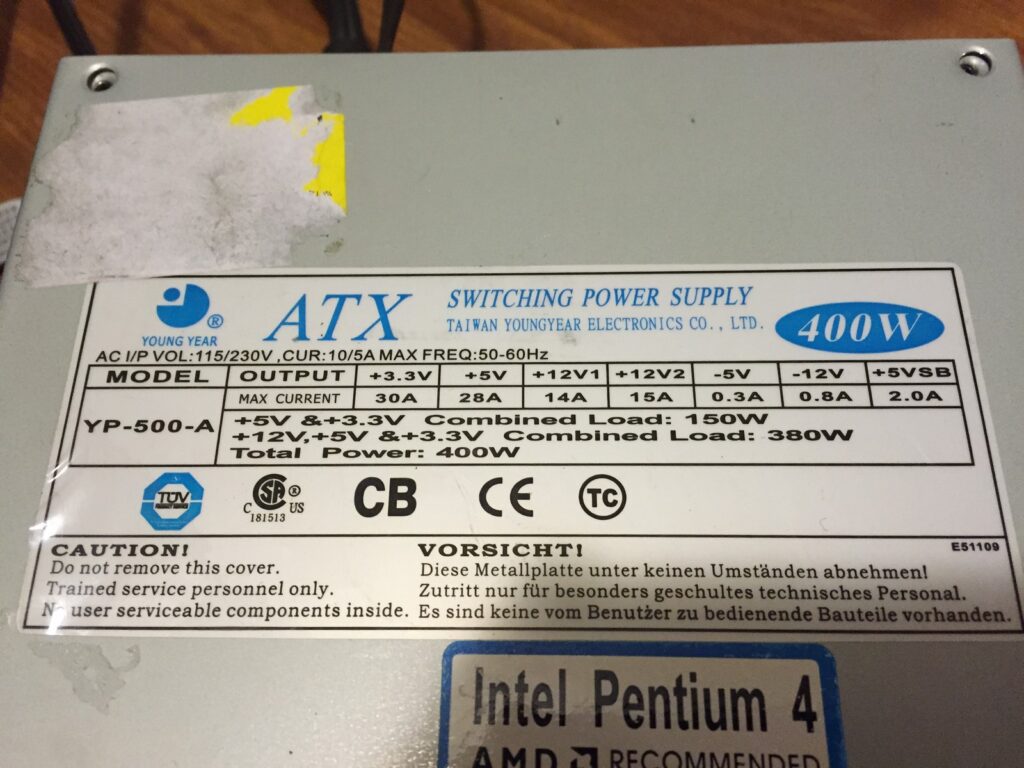
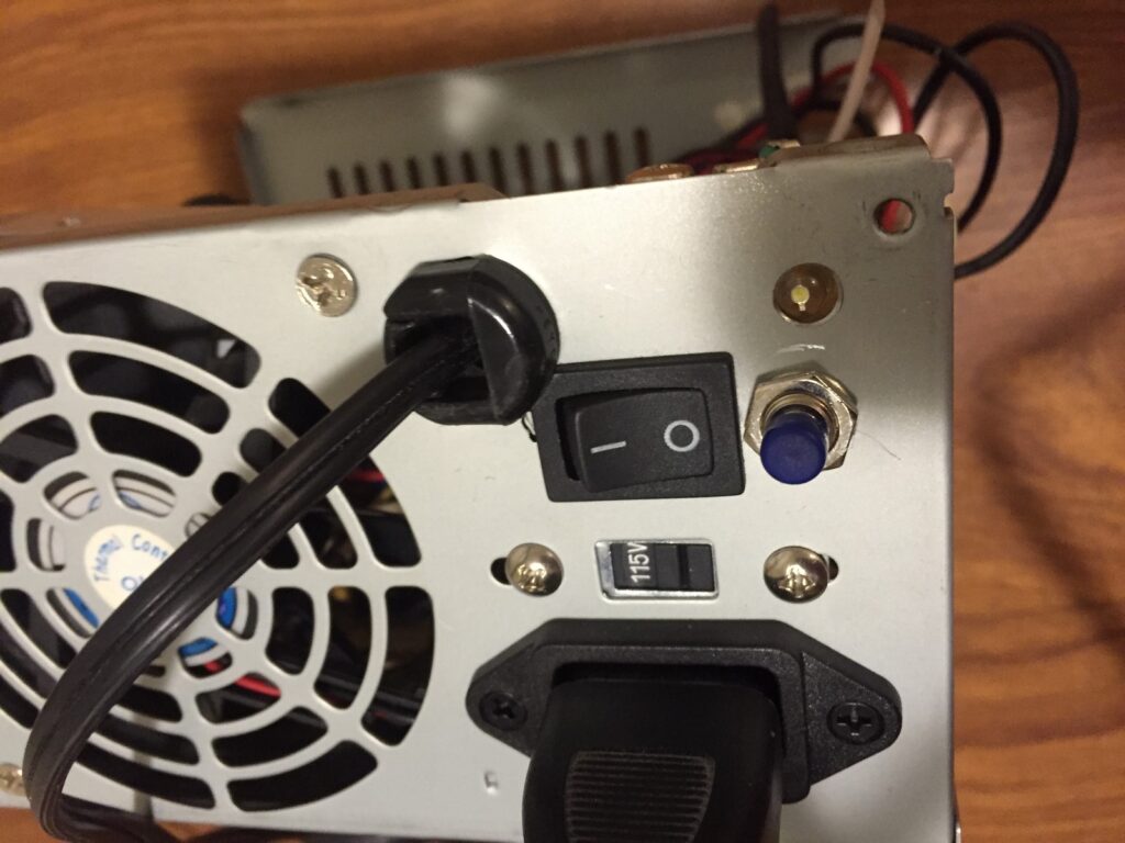
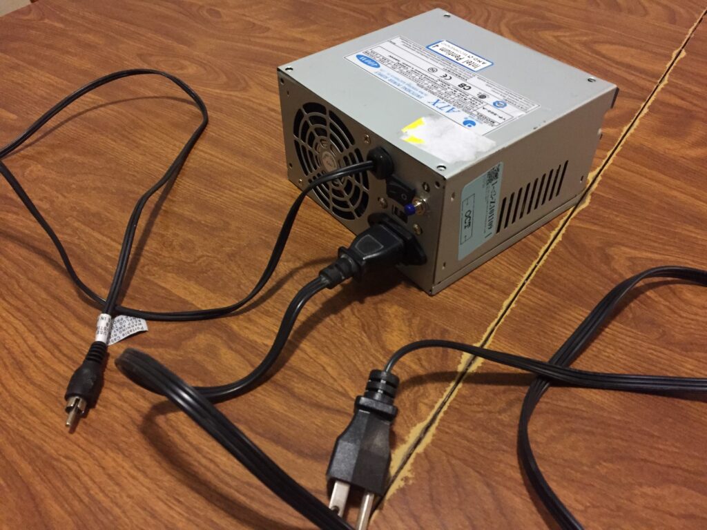
An ATX PSU requires a small amount of modification to be useful for other projects.  This article explains the right way to do it.  I skipped a few steps, simply cut all wires except for a ground (black), +3.3V (orange), and +5V (red).  I also connected the green wire directly to ground so the PSU will turn on as soon as the main power switch on the back (now the front!) is turned on.

The PSU’s 3.3 volt rail was rated for 30 amps.  The idea was to control the 3.3 volt output with a MOSFET.  This provides the correct power output without damaging the PSU.  I selected a MOSFET with a low gate capacitance so that an ATTINY85 microcontroller could drive the gate at high frequency.  Mistake!  After hooking up the 3.3V output to a pen and driving the IRL540N’s gate without any resistors, an oscilloscope revealed significant voltage spikes (>40V) when the transistor was energized and de-energized.
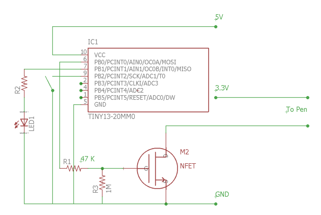
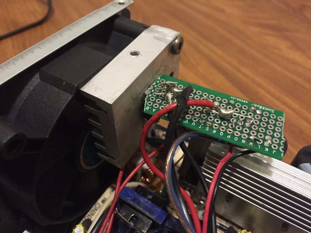
So, I kept using the same transistor but added a 47K ohm resistor between the microcontroller and the transistor’s gate.  A few resistors were experimented with first.  A 47K ohm was the lowest to completely eliminate the voltage spikes.  The slow state change resulted in a significant amount of heat from the transistor, so I found a suitable heatsink from another junked electronic board and mounted the transistor on it.  The transistor and controller were mounted inside the PSU with the heatsink adjacent to the fan.  Just to be sure that the brutality to the PSU was minimized, the PWM frequency was kept very low.  Driving the transistor at about 50 hertz did not seem to affect the pen’s performance.  I haven’t experimented with even lower frequencies to see how low it could go.
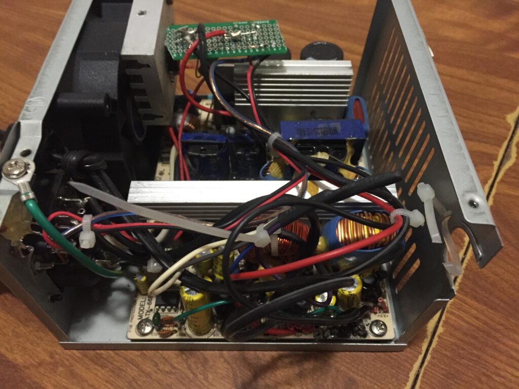
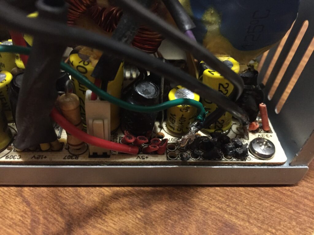
The heat output was controlled by pressing a button mounted on the PSU case beside the power switch.  It has five settings, which can be re-programmed after the unit has been field tested.  An LED indicates the station’s status.  The logic portion of the unit is powered by the PSU’s 5V rail (so that it’s separated from any power irregularities on the 3.3V rail).  The 5V rail also has a low-resistance, high-power dummy resistor to keep the switching power supply stable.
As for a cable, the pens connect to the station via a basic RCA connector.  I happened to have an RCA cable handy, so I simply cut one end off and connected it to the station.  About 2 feet of cord is sufficient, and can be extended if there are any complaints.
Firmware:

Here’s the Arduino Sketch.

//Written by Tyler Gerritsen
//2017-10-21

//Version 1.1 (Release 2018-02-19)
//Much cleaner code
//LED heartbeat function

//Pyrography Pen Power Supply Controller
//Written for ATTiny85 w/ Internal 1MHZ Clock

//One short button press = increment PWM output
//One long button press = turn off output


//Set your ATTiny85 Pinout Here
#define BUTTON_PIN 2
#define LED_PIN 1               //Needs to be PWM
#define POWER_OUTPUT_PIN 0

//Set your Button settings here
#define BUTTON_DEBOUNCE 400       //Debounce time
#define BUTTON_LONGHOLD 1500      //Time to hold for secondary button function

//Set your PWM settings here
#define OFF_TIME_MICROSECONDS 5000                            //Single value time off duration
#define ON_TIME_MICROSECONDS {6800, 6300, 5800, 5300, 4800}   //Array of time on durations - list size may be increased
#define ON_TIME_OPTION_COUNT 5                                //Number of values in above array


//Global Vars
const byte btnPin = BUTTON_PIN;
const byte ledPin = LED_PIN;
const byte pwrPin = POWER_OUTPUT_PIN;
byte powerLevel = 0;


void setup() {
  pinMode(btnPin, INPUT_PULLUP);
  digitalWrite(btnPin, HIGH);
  pinMode(ledPin, OUTPUT);
  pinMode(pwrPin, OUTPUT);
  digitalWrite(pwrPin, LOW);
  analogWrite(ledPin, 0);
}


void loop() {
  runBurner();
  checkButton();
  blinkLED(-1);
}


void runBurner(){
  static unsigned long _nextChange;
  static boolean _onOff;
  static const unsigned int _onDelay[ON_TIME_OPTION_COUNT] = ON_TIME_MICROSECONDS;
  
  if (powerLevel){                        //Burner is on
    if (micros() > _nextChange){          //Timer is up - Toggle pin on/off
      if (_onOff){
        digitalWrite(pwrPin, LOW);
        _onOff = false;
        _nextChange += _onDelay[powerLevel];
      }
      else {
        digitalWrite(pwrPin, HIGH);
        _onOff = true;
        _nextChange += OFF_TIME_MICROSECONDS;
      }
    }
  }
  else if (digitalRead(pwrPin)) digitalWrite(pwrPin, 0);  //Burner is off
}


void blinkLED(int8_t blinks){
  static byte _blinks = 0;
  static unsigned long _nextEvent = 0;
  static const byte sineWave[32] = {0, 3, 10, 22, 38, 57, 79, 103, 127, 152, 176, 198, 217, 233, 245, 252, 254, 252, 245, 233, 217, 198, 176, 152, 128,103, 79, 57, 38, 22, 10, 3};
  static byte _sineWavePosition;
  static byte _ledOn;

  if (blinks > -1) {             //Start blinking
    digitalWrite(ledPin, LOW);
    _nextEvent = millis() + 600;
    _blinks = blinks;
    _sineWavePosition = 0;
  }
  
  else if (millis() > _nextEvent){    //This is the timer, it controls the blink speed and the heartbeat speeed
    if (_blinks){                     //Toggle LED on/off after timer is  up
      if (_ledOn){
        _ledOn = 0;
        digitalWrite(ledPin, LOW);
        _blinks--;
        _nextEvent += 150;
        if (!_blinks) _nextEvent += 600;
      }
      else {
        _ledOn = 1;
        analogWrite(ledPin, 10);
        _nextEvent += 150;
      }
    }
    else {                    //Heartbeat
      _sineWavePosition++;
      _sineWavePosition %= 32;
      analogWrite(ledPin, max((sineWave[_sineWavePosition] / 10),1));
      _nextEvent = millis() + 50;
    }
  }
}


void checkButton(){   
  byte _b = readBtn();  //Read the button (0 = no press, 1 = short press, 2 = long press)
  
  switch (_b){
    case 1:
      powerLevel++;
      powerLevel %= (ON_TIME_OPTION_COUNT + 1);
      blinkLED(powerLevel);
    break;
    case 2:
      powerLevel = 0;
      blinkLED(0);
    break;
  }
}


uint8_t readBtn(){  //Return 1 if short pressed & released, Return 2 if long pressed PRIOR to release
  static unsigned long debounceTimer;
  static unsigned int buttonRead;
  static byte buttonPos;
  
  buttonRead = 1 - digitalRead(btnPin);     //Pin is pulled up
  
  if (buttonRead && millis() > debounceTimer){   //Button depressed
    if (!buttonPos){
      buttonPos = 1;
      debounceTimer = millis() + BUTTON_LONGHOLD;
    }
    else if (buttonPos == 1){
      buttonPos = 2;
      return 2;
    }
  }
  else if (buttonPos && !buttonRead) {
    debounceTimer = millis() + BUTTON_DEBOUNCE;
    if (buttonPos == 1) {
      buttonPos = 0;
      return 1;
    }
    buttonPos = 0;
  }
  return 0;
}

19 thoughts on “Pyrography Power Supply #DIY”

  1. This can almost double as an electrocautery improvised field kit. I was at first envisioning something more like a soldering iron use also, though the specs are a little different and can still be made to work.

    I had no idea the science, art and craft of wood burning or pyrography has advanced. Might be handy for plastic welding also. I still have my pre-teen wood burner out in the garage I found going through stuff. I know I had another one I was using as a soldering iron for a few I left at my other place.

    Seems like lowering the frequency would be more energy efficient I’m thinking if still functionally effective per your requirements.

    Neat and way to go!

    Reply
    • Those are some creative uses! I would like to experiment with the frequency to see when the pulsing becomes noticeable. The tool heats and cools quickly and I’m confident that it would need to be greater than 1 hz for sure. Cheers!

      Reply
      • Thanks! My only hacked power supply (at least other than output wire adapters) is for a 1000W Honda Generator for use with my john boat and canoe instead of a battery for the trolling motor. Basically, I combined all the 12V circuits together to use all the current in one output as well as added a larger fuse. Unfortunately, the john boat and generator were stolen on separate occasions. I do have the power supply still and you’ve motivated me to take a look at it again to see if worth stabilizing the voltage spikes. I have to read into more and might not be a bad idea to make a better bench power supply with a used one if I can find cost effective versus all the wall warts.

        Neat the tools that we can make using electronics and even recycled/re-used/restored older or other items. At times we can even make better than what we can buy off the shelf too. In regards to the frequency… I recall some youtube videos years ago where maybe it was Japanese inverters/converters using a lower frequency like maybe even down to 35Hz . There was also someone else who was promoting some sort of variable pulse power supply video also for home appliances and there was debate over causing issues with compressors for refrigerators or air conditioning units that use compressors. Other than that.. is an interesting way to save energy if your device is effective. All the best!

        Reply
  2. Hello Everyone

    I have been reading this tutorial and i built my own bench power supply, I was reading this because i want to have this integrated in my power supply, I not supper savvy in electronics but I understand most of the schematic that is here, except for R1 and R2, what is R2 ohm? And what is both of their watt? I would really appreciate it if some can help with this and post a pic of the final pcb soldered with this components, the switch I suppose it doesnt matter how many amps it is

    Thank again cheers

    Reply
    • R1 = 47k, 1/4W.
      R2 is dependant on your LED. First of all, the controller cannot provide more than 40mA per pin (and really shouldn’t do more than 20mA). So, use an LED with 20mA forward current or less.
      A 1/4W resistor will be fine. You can use an online calculator to figure out the resustance, here’s one: https://www.digikey.ca/en/resources/conversion-calculators/conversion-calculator-led-series-resistor
      If you don’t have your LED’s specs (like me, since mine came from eBay) you could just try a 200 ohm resistor. If it’s too dim, try 100 ohm.
      I can add photos of the PCB later!

      Reply
      • thank you so much for your reply I have been trying to do this and I already got most of the items I need to get this working, I would love to see pictures of the PCB as it would give me a visual of what it has to look like cant wait… I have more questions since I have been reading your tutorial. on the schematics you skip numbers 3 and 8 for the cables that go connected to the wires is there a reason why? also something I have been looking at in your arduino code you have

        const byte btn = 2;
        const byte led = 1;
        const byte pwr = 0;

        but on the schematics you have pb1 to button and pb2 to led or am am wrong?

        and my last question sorry, would it be possible to change the button to change the temperature for a potentiometer or a switch with different settings? this is so I can go back and forth instead of having only one way up this would be very helpful to integrate. I am sorry if I am havig too many questions, but I really want to make one like this. I already built a bench power supply with an lt3780 with variable voltage and current, this didnt work for my pen since it shorts the power supply and also blows the fuse on my lt3780, I am using nichrome cable on my pen. Once I have everything I ordered I will be documenting everything so others can accomplish this.

        I really appreciate your answer and hope you can clear some of my other questions

        Reply
  3. I don’t know why numbers 3 and 8 are skipped, this was made using Eagle (which I am admittedly a novice at).

    Good catch! The schematic is wrong, the LED pin MUST be connected to a PWM pin (either 0 or 1). See the updated schematic, and note the new pull-down resistor for the MOSFET (just an extra safety precaution to turn off the MOSFET if something goes wrong). Also, I updated the Arduino code with the edits I’ve made over time, please use the new Arduino sketch. it should be easier to read and adjust.

    Using a potentiometer – YES! I prefer the button because it’s very repeatable (I know setting #4 is great for general purpose, and I can always go straight to that setting without trying to dial a pot). If you want to modify the code or write your own, go for it! You will need to build a new low-frequency PWM function, as mine only has 5 options.

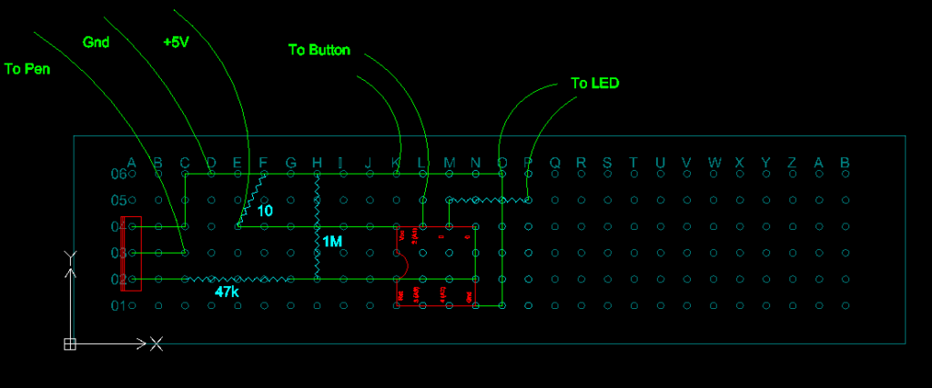
    The control board is covered with hot glue (prevents shorting to the power supply case) so I cannot get photos. You can now find a diagram of the circuit board on this page.

    Good luck!

    Reply
    • I am honestly forever so grateful, I am glad we got to update code and schematics here and also get the actual pcb picture which honestly helps a ton, I should be getting all my parts through this week and will be reporting back. for me to include a potentiometer I will have to learn more about coding as I am not so experienced on this field but extremely eager to learn I will be analyzing the code and schematics and hopefully everything will come out great. thanks again best wishes

      Reply
  4. Hello there me again, so I finally got all the pieces and put it together everything works perfect I messured with my multimeter and voltage comes out button works everything is good, except that when I plug the pen I made with nichrome wire it automatically shuts off, now I am more than sure what is causing this issue is my power supply, it turns off because it thinks its a short circuit, I read in some forum that there is a chip that does this but I dont know where to star, any help with this would be greatly appreciated. I already have a 47k 10w resistor connected to the 5v rail, please if you have any insight of what could be causing this I would really appreciate it

    Reply
  5. The first thing is you should have a different resistor between your power supply 5v rail and ground rail. I think 10 ohm 10w was recommended by the linked article. 47k will not work.
    Also, check that none of your electronics are touching and shorting to the PSU case.
    You are using a home made pen? If so, check its resistance with a multimeter. Since amps = volts / ohms, divide 3.3 / your measured resistance. Make sure the answer is less than your PSU’s 3.3v rating.
    If you are still having trouble, it will need to be diagnosed with a multimeter.

    Reply
    • So I was doing some google searches and I found the following article which is very interesting, I am not sure if I am allowed to add links but here it is

      http://burnt-traces.com/?p=159

      on this article the author states that the under/over voltage chip shuts the power supply off automatically when the power supply is used for the purpose we are using it for,in his case a 3d printer. I ordered a new resistor, but if I get the same problem i will have to do what these guys did, it is a homemade pen and I am using nichrome wire for the tip. when I test for resistance it reads 0.2 which gives me an amperage of 16.5 which is less than the psu rating..

      I wont give up on this and will keep trying to get this to work

      when testing the output voltages of all the rails I get an accurate reading of all of them I dont think its the power supply but the controller that makes it go off automatically

      what do you guys think?

      Reply
      • Most (all?) PSU’s won’t operate without a load on the 5V rail (The pen is on the 3.3V rail and doesn’t count). Fix that by adding a suitable resistor between 5V and GND, then go from there.

        Reply
  6. Hey so I got the proper resistor and i am still having the same problem, I am starting to think it might be the pen that is giving the problem, I made it at home and might be casing the issue, I tried 2 different power supplies and I am still having the same problem on both PSU I dont know what else to try, can I use another rail? instead of the 3.3v? I used nichrome wire to build my pen… I am also thinking on trying to lift the pen from the power management chip to try my luck, if that fixes y issue i will report back here

    thanks

    Reply
  7. For those having the same problem as Gabriel, I needed to put a significant load (10 ohm, careful with resistor ratings) from both 12V-GND, and 5V-GND.
    This allowed me to pull high currents from the 3.3V rail.

    Reply

Leave a Comment