A FULLY Plug-and-Play Tally Light
My church (like many others) recently began streaming sunday services. The staff had quite a job on their hands adjusting from a live audience with a small online presence to an online-only presence. Subtle communication between the ‘techies’ and ‘actors’ was difficult, but a simple tally light made it simple to send a queue to the staff on camera automatically. A tally light is simply a light that turns on when the camera is recording.
This tally light is a simple Raspberry Pi-based system which connects with OBS Studio over the network and illuminates a lamp when the camera is live. The system does not need any external input – it will find OBS studio and save its address for future sessions. If OBS studio moves to another PC, it will still find it. The camera illumination is configured in OBS studio, so no need to change anything on the tally light. Finally, if OBS Studio gets disconnected for whatever reason, the tally light will turn off and the Pi will immediately begin searching for OBS Studio again.
Update 2020-07-13 – Greg Cotton made some modifications to the Python script so that one Raspberry Pi can control multiple tally lights! His code and circuit diagram is available at https://github.com/SiliconKnight42/OBS_TallyLight.

An optional status LED on the circuit also indicates if the tally light has booted and whether it’s connected to OBS studio.
Hardware
- Raspberry Pi – I used a Pi 3 B as the facility only uses 5GHz wifi, but a Pi Zero W will also work if the network has 2.4GHz wifi.
- 4GB or larger MicroSD card
- 5V USB supply or XL4015 Buck Converter
- IRF540N MOSFET
- 220-ohm, 47K-ohm, and 100K-ohm Resistors
- 5mm indicator LED
- LED Strip and Power Supply
OBS Studio Setup
- Go to https://obsproject.com/forum/resources/obs-websocket-remote-control-obs-studio-from-websockets.466/, click Go To Download, scroll to the bottom, and download the appropriate package (depending on your OS)
- With OBS studio closed, install the package
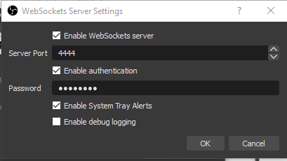
- Open OBS Studio, go to Tools, then to Websockets Server Settings
- Change the password to 123456 (Or a unique password, then copy the password in the Python script below)
- Make sure the port is 4444
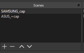
- In your scenes, rename all the scenes that you want to illuminate the tally light so that it includes a ‘+’. That character is the tally light’s signal to turn on.
- If you want to use a different character, or use multiple tally lights with unique characters, then that’s totally fine. Just be sure to edit the python code accordingly.
Raspberry Pi Setup
I’m going to give you this part recipe-style:
- Burn the latest version of Raspbian Buster Lite to a microSD card. I use Banana Etcher to do this.
- Go to the Boot drive on the card and create a file called ssh. Don’t edit it.
- Now create another file in the Boot drive called wpa_supplicant.conf and open it with a text editor. Save the following text (Note that country=ca is for Canada, use country=us for USA, etc.):
- country=ca
update_config=1
ctrl_interface=/var/run/wpa_supplicantnetwork={
scan_ssid=1
ssid=”NETWORK_NAME”
psk=”PASSWORD”
}
- country=ca
- Insert the microSD card into the Raspberry Pi and power it up. Connect to it via SSH using Putty.
- Change your password!
- Update the system: sudo apt-get update and sudo apt-get upgrade
- Install Python 3 and pip: sudo apt-get install python3 python3-pip
- Install the following Python 3 modules: sudo pip3 install websocket-client obs-websocket-py RPi.GPIO pythonping multiping
- Create an empty text file to store the last OBS Websocket address: sudo nano /home/pi/OBS_address.conf
- You may enter the OBS Studio PC’s IP address into the text file. It will speed up the search, but isn’t necessary.
- Set ownership and permissions on that text file: sudo chown -pi /home/pi/OBS_address.conf and sudo chmod 777 /home/pi/OBS_address.conf
- Create the Python script: sudo nano /home/pi/tallylight.py
- Copy the code from my repository (if you want to use multiple tally lights, then go to Greg Cotton’s repository). Save with Ctl-X Y.
- Edit the trigger_char variable if you don’t want to use the ‘+’ character as a trigger
- Make sure the password matches what was set in OBS Studio
- Set the code to execute on boot: sudo raspi-config , Boot Options, Desktop/CLI, Console Autologin, Finish (don’t reboot yet)
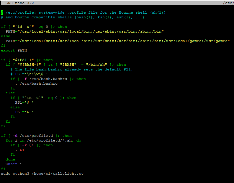
- Edit the boot script: sudo nano /etc/profile, and add this line at the very end: sudo python3 /home/pi/tallylight.py
Hardware Setup
I used a surplus LED from my high-speed flash testing. It’s moderately bright (~4,000 lumens) and has a 28-volt forward voltage. It’s switched by an IRF540N MOSFET transistor which I have previous experience with. This MOSFET is great for 3.3V logic: it’s a sturdy power MOSFET but its gate-source threshold voltage is fairly low. You can probably carry an amp or so with it (and switch up to 100 volts!).
You can run the Pi with a 5V supply and your LED with another supply (as shown above), but I chose to run both from a 32V supply. A XL4015 buck converter takes the 32V power and supplies a nice clean 5V to the Pi. Those buck converters are surprisingly reliable – I have the exact same one powering my ethernet switch at home since the original power supply died!
Below is a hand-drawn schematic for my system. If you are using Greg Cotton’s script, then please see his schematic.
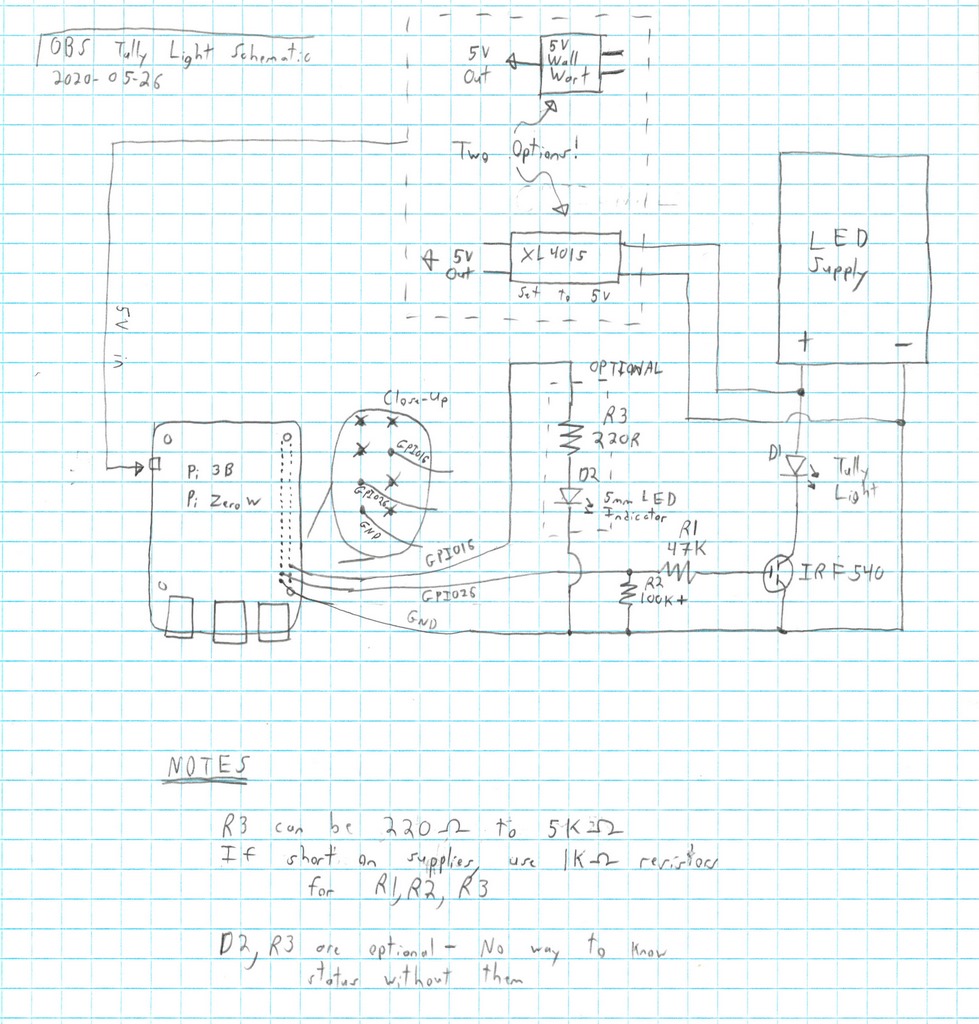
The LED indicator circuit attached to GPIO16 is optional. I would recommend it, otherwise the only way to know that the system is booted and connected is to test the tally light, which might not be convenient when other activities are happening. Two options for supplying the Raspberry Pi are also shown. The ‘wall wart’ is simpler but requires more than one plug. The XL4015 (or similar) buck converter needs to be mounted, set to 5V, and soldered onto the Pi. However, the second option looks cleaner with only one plug required.
The LED supply needs to match your LED’s. If you use a 12V LED strip, then connect them to a 12V supply (surprising right?). I opted for a powerful Bridgelux LED which required a 32V supply and series resistors. If you’re not familiar with designing LED power supplies then I would suggest using the 12V strip.
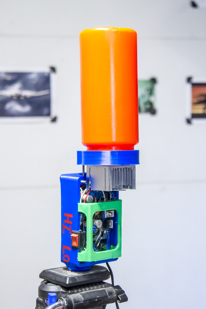
Here’s a picture of my tally light. That is a ketchup bottle on top! Turns out that the ketchup bottle has a metric thread which was very easy to 3D print. The LED current is controlled by an LM317 with a current-sense resistor. The resistance is controlled with the switch on the side.
Shoutouts
Thanks to Elektordi with his OBS Studio websockets Python module! His module is licensed under the MIT License.
Also thanks to jbrendel for his multiping Python module. Apparently you can ping hundreds of IP addresses simultaneously – awesome!
As mentioned, thanks to Greg for expanding the code to allow multiple tally lights.
Troubleshooting Tips
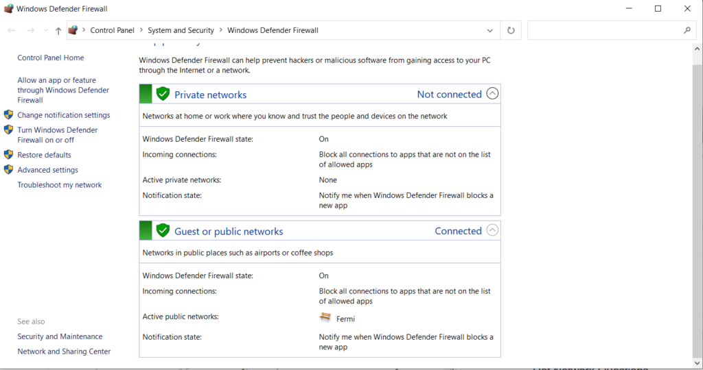
I came across an interesting problem. If you are using Windows and the network profile is ‘Public’ then Windows will not reply to any pings from the network (the Tally Light relies on a ping response to find OBS Studio). Below is an example where the network profile is ‘Public’ – I had to change it to ‘Private’ in order to make Windows reply to pings.
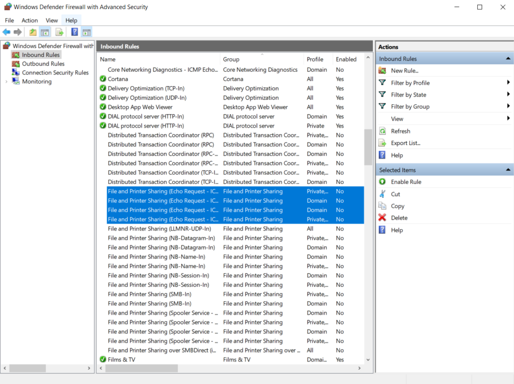
Next, I had to turn on ping replies (under Advanced Settings in the dialog above). Below is a screenshot of the Windows firewall before I turned on ping replies. The selected items need to be Enabled.
Last updated 2020-09-08