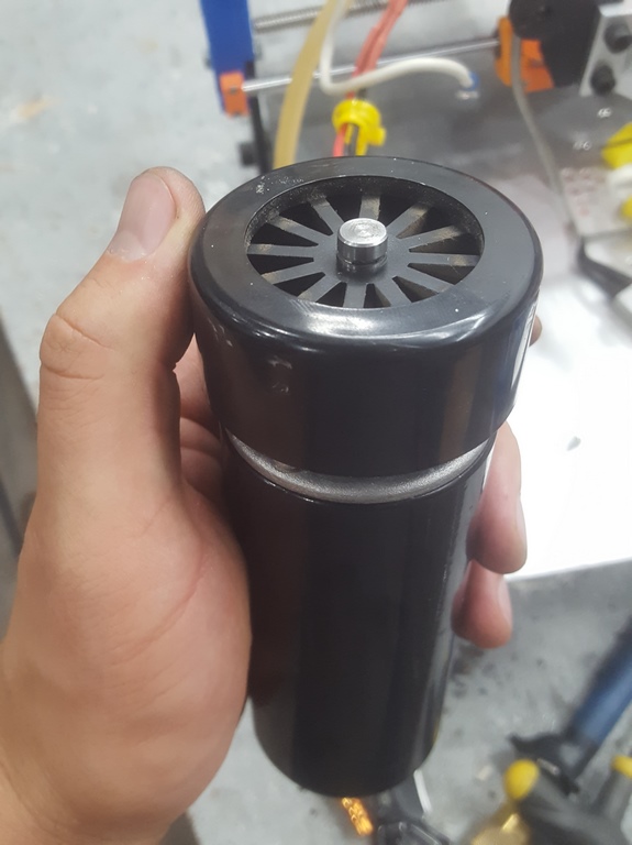
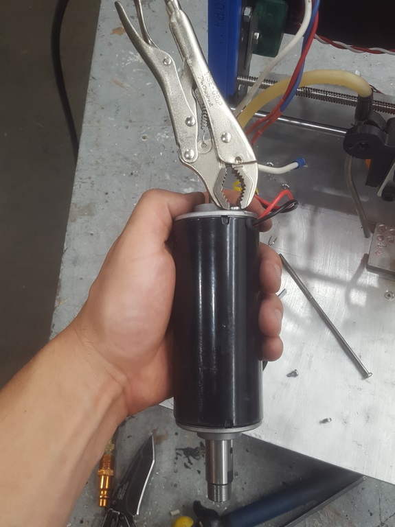
While building my CNC mini-mill, I purchased a 500W air-cooled spindle from eBay. It came with a power supply, which looked great and I (falsely) assumed it would work perfectly on my home-built mill.
Boy was I wrong! The mill worked great as long as the spindle was turned off. Whenever the spindle was on, there was a chance that the mill’s microcontroller would reset (bad), lock up (worse), or would suddenly enter an infinite loop (really really bad!) and an axis motor would begin moving in some direction until I noticed and stopped it.
After much work identifying and rectifying the causes, the power supply has finally been tamed. Here’s a guide for anyone having the same issues.
The Mill Controller
For context, my mill controller is home-designed and built from a pre-drilled perfboard. It runs on 12 volts, which are supplied from an ATX power supply. The power supply works well whenever the spindle isn’t on, and temporarily swapping it out with another ATX power supply has never rectified the issue. The ATX power supply is supplied from the same 110-volt AC circuit as the spindle power supply.
The 12V rail feeds three stepper drivers (A4988’s and DRV8825’s) and an LM7805 voltage regulator. The regulator delivers 5V to the ATMega328P microcontroller, LCD display, SD reader, and the rest of the peripherals. A heatsink on the regulator prevents thermal overload from occurring.
The spindle is controlled by an opto-isolated relay. The wiring is routed so that the spindle’s control wires don’t pass near the controller.
The firmware is my own home-brew. I know the bugs have been worked out of the firmware as I can ‘dry run’ a CNC job (with the spindle turned off) successfully without issue.
The Symptoms
The three primary symptoms (briefly described above) are as follows:
- Hard Reset. Occurs frequently. The microcontroller will behave as though its reset pin has been toggled. The spindle turns off and the position display shows 0,0,0.
- Freezing. Occurs occasionally. All motion ceases. The spindle remains turned on and the position doesn’t change. The controller doesn’t respond to user input.
- Infinite Looping. Has only happened a couple times. The controller begins moving an axis in some random direction indefinitely. the display doesn’t update and the controller doesn’t respond to user input.
These symptoms ONLY occur if the spindle is turned on. They are also very random: the mill can complete a 1-hour job without any symptoms occurring, but may also reset a few minutes or seconds after turning the spindle on. Varying the speed of the spindle doesn’t appear to affect the rate of occurrence.
Interestingly, The issues seem to be worst when the spindle tool is in contact with a metallic workpiece. Also, on one occasion the machine was plugged into the same outlet as my 3D printer. It was resetting frequently until I plugged it into a separate circuit from the printer, at which point it ran for an hour without issue.
The Causes
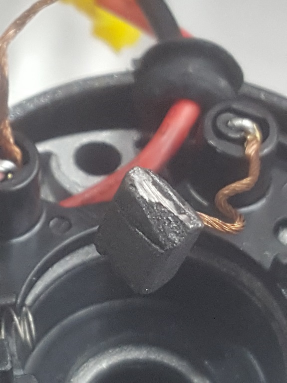
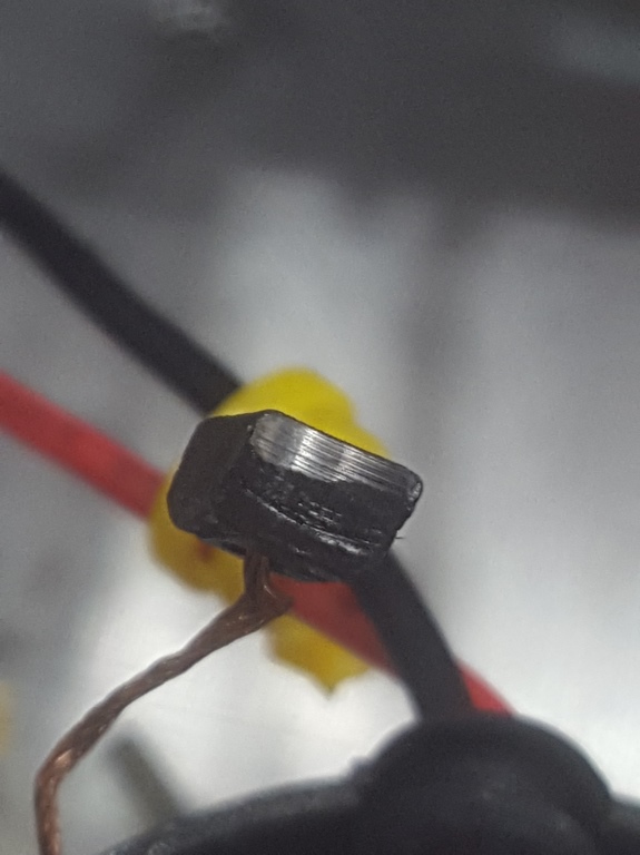
The spindle and power supply came pre-loaded with two problems. First off, metal filings inside the spindle motor were causing intermittent shorts between the commutator / coils and the spindle. This meant that the tool was being charged and discharged, causing power fluctuations whenever it touched the workpiece. I noticed this after getting a mild zap when I touched the spindle one time.
Second, the power supply was a very crude design which introduced power fluctuations in the supply power. The supply works by rectifying the AC power and smoothing it with a capacitor. The spindle motor is connected to the rectified power through a MOSFET, which is turned on and off to control speed. A flyback diode is also present. The MOSFET turns on and off very quickly, causing voltage spikes whenever it changes state. Because there isn’t an isolating transformer, the circuit cannot be grounded to the case in any way as the rectified voltage is constantly moving above and below ground voltage (IE. rectified negative moves between 0 and -110 volts, while rectified positive moves between 110 and 0 volts).
The Solutions
Following are the modifications I’ve made to prevent the symptoms from occurring. I’ve ordered them from most helpful and easiest to the least helpful and most difficult.
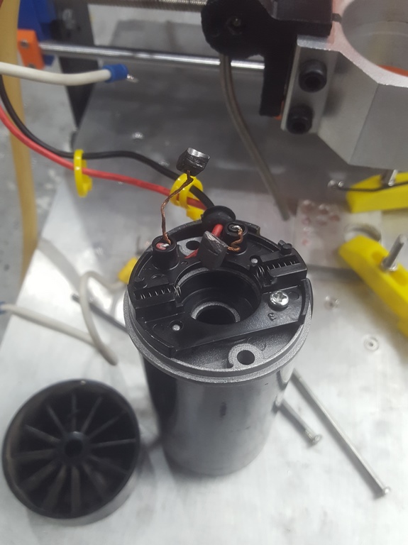
- Clean The Spindle (very helpful, moderately easy). I disassembled the spindle (which isn’t hard) and discovered two problems: There’s an open hole in the top and a chunk of metal filings inside. I also noticed the brushes look terrible, but there’s not much I can do about that.
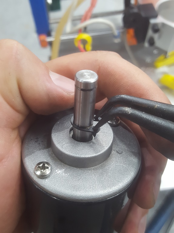
- Remove the C-clip above the fan
- Remove the Fan (pull hard!)
- Remove the C-clip below the fan
- Remove both screws
- Push the brushes in to slide them past the commutator and bearing
- Blow out the entire motor very good!
- Reverse the instructions to re-assemble the motor. You will need to use vice grips on the main screws to line them up, since there are no guides.
- Cover up that huge hole with some duct tape.
The Results
I haven’t had much runtime since making all of these modifications, but the issues seem to be resolved (if I don’t overload the spindle). I will update this post with any more modifications I make.
Last Updated 2019-08-26
1 thought on “Cheap Spindles & Power Fluctuations”