2019-07-25 – The list price of the well-designed Vela One has recently dropped. I originally quoted it at about $1,750 CAD but unfortunately don’t have any proof. As of today, the Vela website indicates it is exactly $1,526.70 CAD. The archive.org website shows that the price has indeed fluctuated over time.
2019-08-01 – A big THANK YOU to NQTRONIX who has kindly gifted me an active light probe of his own design. The probe will be used with an oscilloscope to measure the flash duration, trigger response time, light output -v- current, and other helpful things. I will update this post with the data once testing commences. NQTRONIX put a TON of time into designing, testing, and optomizing his probe. Please consider checking out his instructable page and leaving him a like or comment!
2020-07-01 – The ‘Mark 2‘ high-speed flash is complete! The plans are available to build your own, or contact me if you’re interested in purchasing a strobe. I’m focusing my development on the new E2-A and promoting it as a replacement for the original Edgerton strobe.
- If you’ve put money and effort into building the original Edgerton flash, please continue using it as it has the same performance as the newer E2-A.
- If you are considering building a strobe, I would encourage you to use the newer E2-A design as a more robust design.
- If you are set on building the original Edgerton strobe in order to save a few $$, then the main control boards are available at https://www.tindie.com/products/19592/.
2020-07-03 – I’m realizing that the following notes should have been added back when I first made this post, but better late than never. I’ve personally never experienced a catastrophic LED failure during normal use, but at the same time I feel potential users should be made aware.
IMPORTANT NOTE #1: This strobe pushes the capabilities of the LED’s. Complete failure of the LED’s is possible. That means the expensive components can be accidentally destroyed and require replacing. I’ve taken many precautions in the design to prevent this, but please consider building a strobe at your own risk.
IMPORTANT NOTE #2: The LED’s are not as powerful as a Xenon flashtube, and they do not turn on as long as a typical camera strobe. Expect to crank up the ISO by several stops (4 or more) in order to capture usable images.
EDGERTON
Named in honour of the legendary Papa Flash.
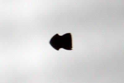
Some time ago I designed and built a ballistic chronograph and used it to take some high-speed photos of bullets striking glass. The results were great, but the photos were somewhat limited by the standard ‘speedlight’ flashes that I used – there was always some motion blur. Edgerton is a ‘High-Speed Flash’ which uses LED’s to make one-microsecond flashes to freeze motion.

High-speed photography is no recent invention. Doc Edgerton was already experimenting with high-speed photography in the 1940’s, and has taken some incredible photos. He was known to use (among other equipment) an Air-Gap Flash, which is similar to the Xenon flash tubes found in modern camera equipment. It unfortunately requires much higher voltage which could easily cause injury (SEVERE injury). While I didn’t completely disregard the option, I eventually opted for a safer solution.

A recent kickstarter campaign (Vela One) offered a high-speed LED flash. It can produce flashes lasting 0.5 μs (microseconds), was not dangerous, but was priced about $1,750 $1,500 CAD! Similarly, other internet hobbyists have documented their experiments with LED’s for high-speed photography (notably petermobbs.wordpress.com and tomscircuits.blogspot.com). I did some testing with a single LED and came up with similar results. I’m documenting my attempt at building a full-scale flash and sharing the plans to manufacture your own copy.
A Little Science
There are three requirements for a high-speed flash: light power (luminous power), beam focus (viewing angle), and flash duration. Luminous power is the total power output from a source, while luminous intensity is the amount of power per radial angle.
Because the luminous power and viewing angle are constant and do not change with flash duration, increasing the flash duration also increases the total light output (exposure). The response time (time to turn ON and turn back OFF) of all the components are discussed below. I limited the flash duration to between 0.5 μs and 4 μs, selectable in one-stop increments (0.5 μs, 1 μs, 2 μs, and 4 μs).
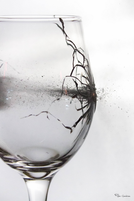
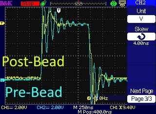
Below is a comparison of a typical camera flash vs this high-speed flash (1-μs duration). Both air rifle pellets were fired from the same rifle, traveling about 280 m/s. This demonstrates the advantage of using a high-speed flash for high-speed photography.

Components
Below is a partial parts list. All prices in CAD. Total cost: About $165. The complete bill of materials can be found at the Github repository.
- 12x CREE CXA2530-0000-U20E3 LED’s (datasheet) – $6.66 ea.
- 4x Vishay MKP1848S 10μf Capacitors (datasheet) – $6.17 ea.
- 4x INFINEON IPP60R190P6 N-Channel Power MOSFETs (datasheet) – $3.92 ea.
- 45-390V Boost Regulator (no model number, no datasheet – just search the description on eBay) – $10
Controller:
- ATMega328P Microcontroller – $3.31
- LM7805 Linear Regulator (from eBay) – $0.25
- TC4452 FET Driver (datasheet) – $3.38
- TM1637 Four-Segment LED Display (from eBay) – $2
- KY-040 Encoder (from eBay) – $0.50
- AA Battery Connectors
- Various Resistors
- Various Ceramic & Electrolytic Capacitors
- 22-Guage Silicon Wire (multiple colours would be helpful)
Other Hardware:
- Over 500g of 3D Printed PETG (Please find the STL Files here on Thingiverse) – $20
- 1/4″ Rare-Earth Magnets (from eBay) – $1
- Arca-Swiss Compatible Mounting Plate(I milled, but available on eBay) – $5
- 4x M5 x 16mm Countersink-Head Screws & Nuts
- 6x M4 x 20mm Socket-Head Screws
- 3x M3 x 8mm Socket-Head Screws
- 8x M2 x 12mm Socket-Head Screws

Why Not Use Cheaper LED’s?
You may wonder why I use expensive CREE LED’s instead of the cheap LED’s available on eBay. Here’s why: cheap LED’s simply aren’t tough enough to be overdriven (more on that below) the same way that these CREE LED’s can be. I had originally tried several types of LED’s from eBay and found that none of them were useful for high-speed flashes. It would take several eBay LED’s to replace a single CREE LED. This means the CREE LED’s are cheaper bang for buck! It also means that a working flash with knock-off LED’s would be ridiculously large and difficult to control.
I’ve been contacted by a few people who were building a flash with cheap LED’s instead of the CREE LED’s prescribed below. At the time of this writing (2020-03-05), I haven’t heard any success stories from people using cheap LED’s. If you built a high-speed flash with knock-off LED’s that is truly functional, let me know and share some images!
Still don’t believe me? Read the tomscircuits.blogspot.com post where he discovers the same thing. He compared a CREE XM-L LED with a no-name LED and found the expensive LED was worth the price.
One more thing. One of the most valuable parts of this design is the extensive testing done with the CXA2530 LED’s. In order to use a different LED, destructive testing is required and that will cost $$.
Assembly
Detailed assembly instructions can be found at the Github repository.
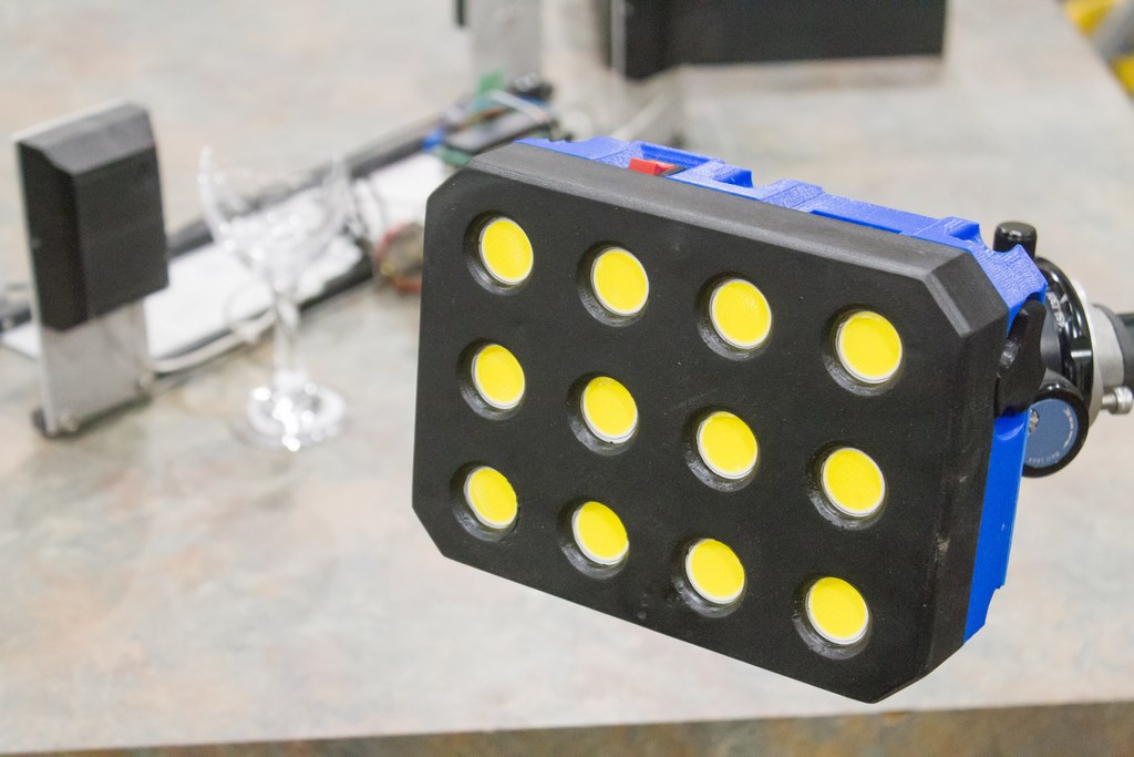
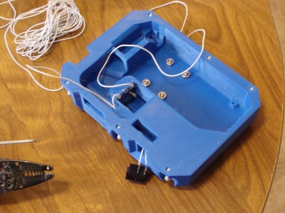
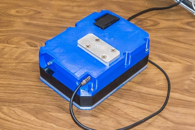
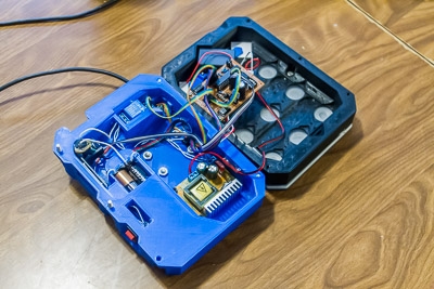
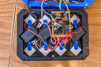
I 3D printed the body in two halves. That’s about half of a spool of PETG and over 30 hours of printing! The 12 LED’s are configured in four banks of three LED’s. Each bank has its own capacitor and MOSFET.
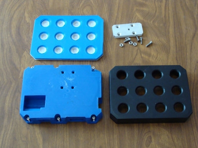
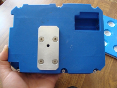
An aluminum Arca-Swiss compatible plate is mounted on the back. It also has a 1/4″ threaded hole so it can mount on tripods without the Arca-Swiss mount.
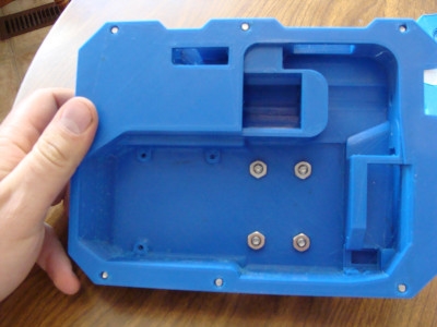
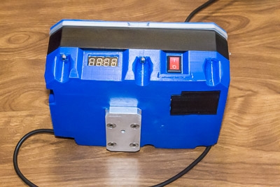
The two halves of the case screw together with six M4 screws.
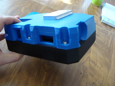
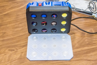
The front half has two embedded magnets. A cover also has two magnets, so it snaps onto the front and protects the LED’s. The cover will protect the bare LED’s when not in use.
The entire flash is powered with eight AA batteries. The batteries slide into a hole in the case.
A capacitor stabilizes the 12-volt rail. The boost converter has a bit of an in-rush current issue, but the rail is quite stable with the capacitor.
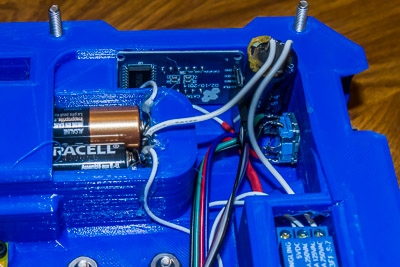
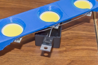
The boost regulator screws into the case and the relay is hot-glued into place. I typically try to avoid using hot-glue for permanent solutions, but options are limited in this case. If I could re-print the case, I would integrate zip-tie holes inside – but a third of a roll of filament and 18 hours of printing is too much to just re-print for one little issue.
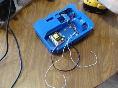
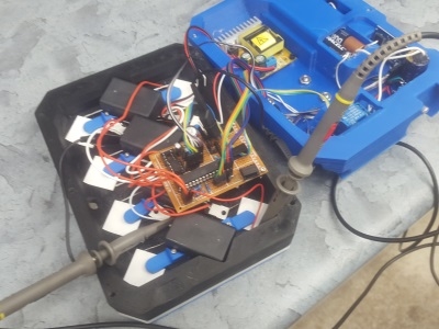
Here’s all of the electronics installed (except of three of the four LED banks).
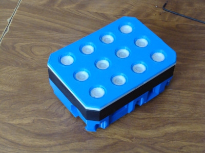
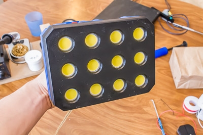
The cover was printed half translucent and has a couple embedded magnets. It snaps onto the body nicely. In this photo I only have one bank of LED’s installed. If something goes wrong during development and the LED’s die, I would rather only lose three instead of all twelve.
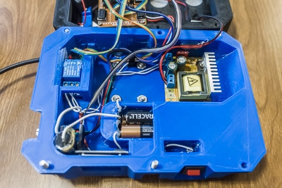
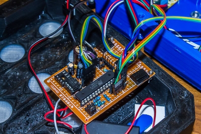
Control Board
The complete circuit diagram can be found in the GitHub repository. I soldered up the control board on a perfboard PCB. Since I hadn’t tested the LED’s to failure before designing the control board, everything was designed for up to 200 V. Since then I’ve strobed several LED’s to failure in order to test how much current they can handle, and 200 V was a pretty good design choice. The boost converter is currently set to 120 V, which is fairly conservative given that I’ve seen them strobe 15,000 times at 125 V without failing and even several strobes at 200 V.
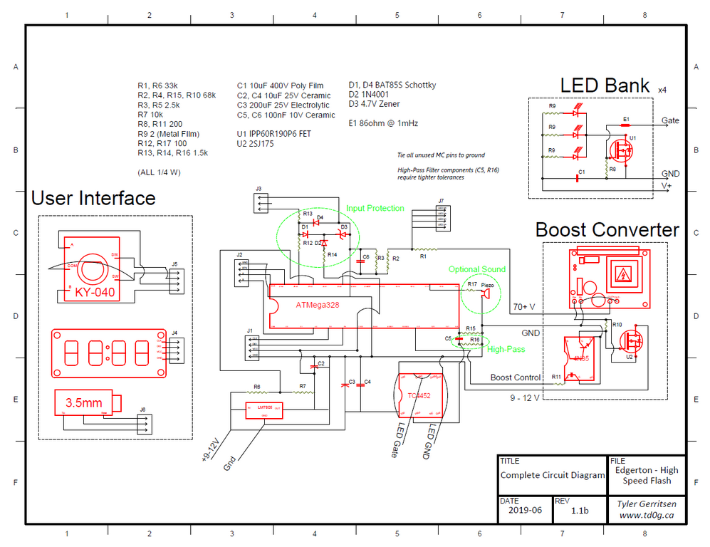
The controller uses an ATMega328P and no external crystal. At 8 mHz, the processor is plenty fast enough to operate the MOSFET driver and user interface.
A major concern is that the microcontroller will reset due to a power fluctuation while the LED’s are energized, since it will take some time for the microcontroller to reset and the LED’s will remain energized until reset is complete.
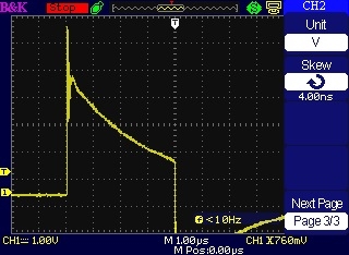
To mitigate the danger, I’ve added additional capacitors (electolytic and ceramic) to the 5V rail, which will stabilize the LM7805’s output. All of the high-voltage rails are kept physically distant from the 5V rail. Finally, I’ve purposely selected a 10 μF capacitor to drive each 3-LED bank. After energizing the LED’s for 4 μs at 60 V, the capacitor loses 12% of its voltage. This is enough to keep the output ~almost~ constant, but in case the MOSFET remains energized, the capacitor should drain completely before too long. Hopefully the LED’s can handle the capacitor’s entire energy reserve without dying!
UPDATE 2019-07-01 The circuit now includes a ‘high-pass filter’ to the MOSFET driver. This simple RC circuit prevents the driver from receiving a signal longer than about 5 microseconds.
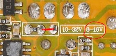
The boost regulator was purchased on eBay. Some of the components had their markings scratched off, but some kind folks have provided a bunch of info on it (including a schematic) at dalmura.com.au and diyaudio.com forum. Unfortunately it originally seemed to require an input of more than 10 V (likely since the UC3842 requires a start-up voltage of about 8.4 V, and the 78L09 regulator has a 1.6 V dropout), so eight NiMh batteries wouldn’t work to drive it. After reviewing the schematics for a while, I thought it would be ok to try bypassing the regulator as long as I didn’t go over 16 V. Then I discovered that the board was actually designed to do this, as shown on the photo below – simply short out the two pads as shown! Now it works on rechargable batteries.
LED’s
The LED’s, capacitor, and MOSFET for each bank are kept physically close to each other in order to minimize impedance in the circuit. I removed the insulation on 22-guage wires and used the bare conductors as high-voltage rails. This is one area I would like to do some more research! As I understand it, using finer stranded wire reduces impedance at high frequencies (the output will have an effective frequency of 2 mHz).
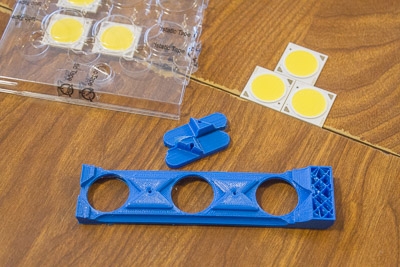
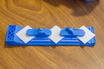
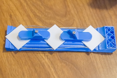
I printed a jig to hold the LED’s during assembly. The hold-down clamps are installed using M2 screws. The odd-shaped triangles on top are guides for the capacitor (which are HUGE!).
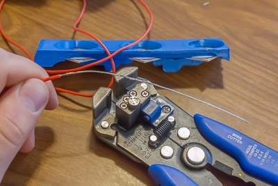
My rolls of silicone 22-guage wire have very fine strands, which are perfect for this application.
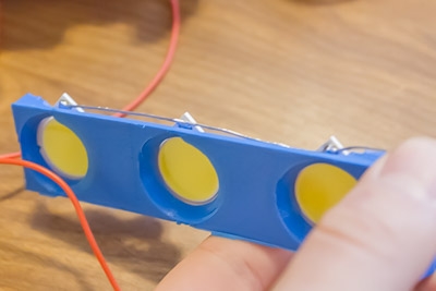
Here’s the positive side of the capacitor and LED.
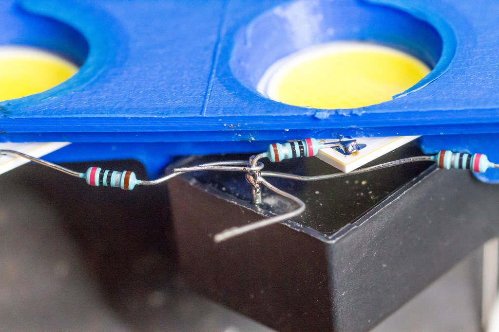
The positive side of the capacitor is tied to the LED’s high-voltage rail through series resistors.
Yeah, it’s a little bit of a mess inside there. I need to print a separator to keep all the high-voltage wires away from the sensitive 5 V components. Note the high-voltage outputs on the lower right corner of the control board can be disconnected, which deactivates an individual bank of LED’s. There’s also an empty DIP-8 socket which is wired up for a second MOSFET driver in case I find one driver isn’t enough for 4x MOSFETs. Turns out that wasn’t needed, one good driver is fine.
It’s pretty!
Over-Driving the LED’s
Most of the cost was in the LED’s. They were about $6 CAD each. I selected the LED by downloading a list of suitable LED’s from digikey, and sorting by luminous flux/$. The Cree CXA2530 series was a good choice, with the U20E3 coming in at 551 Lum/USD$. It has a temperature of 5000K (subject to change under the high-voltage pulse conditions), a rated forward voltage of 37 V, and 115 degree angle of view, it was a solid choice. I anticipated driving the LED’s with up to 200 V (but probably much lower).
The Cree LED’s I used are rated for 1.6 A. When the pulse duration is very short, an LED can handle significantly more power than during constant illumination. See this paper and Cree’s application note on the topic. The Cree application note above advised not to drive the LED with more than 300% of the rated current, but that is for 1 kHz continuous pulsing – not the single pulses used in the flash.
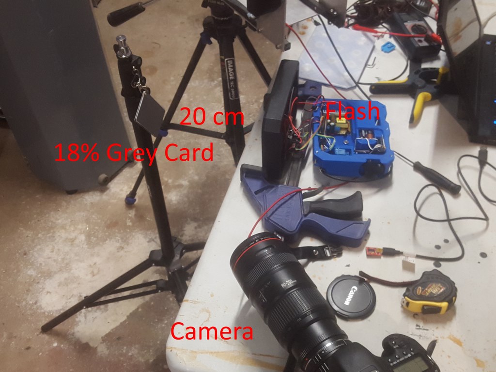
Some tests were done to determine the best voltage to drive the LED’s at. I aimed the flash at an 18% grey card positioned 20 cm away, and photographed the card (which ~almost~ filled the frame) at a constant ISO and aperture (ISO 5000, f/2.8 – max aperture so that there are no variations in diameter) and flash duration (1 μs and 4 μs). The flash was strobed 10,000 times at 1 μs and 5,000 times at 4 μs. The flash’s firmware calculates the average current by measuring the change in capacitor voltage during the flash. ImageJ was automated to analyze the brightness of the centre of each image.
Testing began at 70 V and incremented by 5 V per test. The LED was still functioning at 125 V but I had to stop testing due to limitations on the control board. I did a small number of strobes at voltages around 200 V but did not collect any data. The LED did not fail during testing!
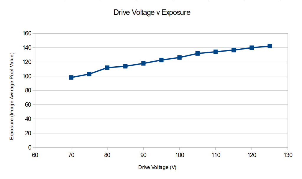
This testing was performed without the series resistors installed. I now have the series resistors included in the design and the voltage is set to 120 V, of which the LED’s receive about 95 V.
Transistors
The ATMega328P is good at generating a 5 V pulse, but there are several higher-voltage components downstream that need to follow suit. The gate driver and MOSFETs need to rise and fall with the signal. The LED manufacturer’s application note says that the LED’s take about 10 ns (0.01 μs) to turn on and off, so they aren’t a problem.
I started with a TC4420 gate driver since it was available in my workshop. It was tested using an oscilloscope. The gate voltage was simple to sample, just clip onto the output. I tested the transistor’s response by sampling the capacitor voltage. If the cap voltage was decreasing, the MOSFET is active.
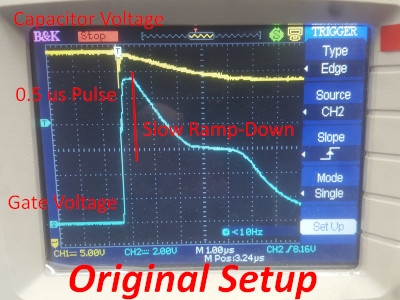
The initial test didn’t look so good. The gate voltage rose quickly, but fell very slowly. I tried adding some resistors between the gate and the source on the MOSFETS (200 ohm per transistor) and a 39 ohm resistor on the control board between the gate driver’s output and ground.
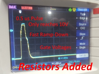
This had the desired effect – the gate voltage fell much quicker. There’s still some lag and the LED’s are being driven too long. This can be accounted for in the firmware by reducing the pulse time. I haven’t done so at this point since it’s reasonably close.
The down side to the resistors is that the gate voltage isn’t as high. It now only reaches 10 V, while it could hit 11 V without the resistors. But the transistors are still conducting, and I can make up for the slightly increased resistance with increased LED voltage.
Eventually I ordered some more powerful gate drivers: TC4452 (non-inverting) and TC4451 (inverting). They were drop-in replacements for the TC4420.
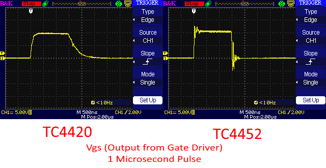
It’s very apparent that the new TC4452 gate driver handles the MOSFET’s much better. I didn’t bother testing the inverting driver after seeing these results. The pull-down resistors are still in place, but I’m not sure if they’re necessary anymore. However there now seems to be some ringing. Based on this application note from ON Semiconductor, it’s probably because I didn’t include a gate resistor, gate clamping diodes, or ferrite bead. Eventually I will experiment with adding these components and post the results.
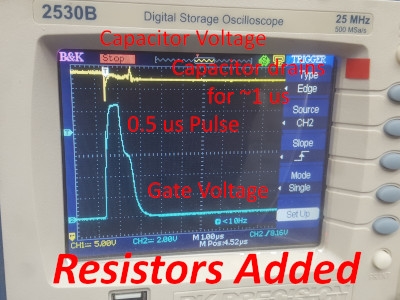
Below is the gate driver output (Vgs) on the left and capacitor voltage on the right. The transistor’s response to the gate driver looks good. I can’t explain why the 500-ns pulse lasts 1 μs and the 1-μs pulse lasts 1.5 μs, while the 2-μs and 4-μs pulses are very close to 2 μs and 4 μs respectively. I’ve recently calibrated the flash durations by adjusting the number of NOP delays in the firmware and checking with the oscilloscope.
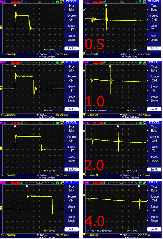
UPDATE 2019-07-01 I’ve recently added ferrite beads in series with the gates. Shown below are the before / after traces and you will note how much the ringing has been tamed:
Additionally, the high-pass filter going to the MOSFET driver prevents the LED’s from turning on for too long. The TC4452 input voltage goes ‘low’ when the voltage falls below 0.8 – 1.3 Volts (per the datasheet). It can also handle negative voltages, so the signal inversion isn’t a problem.
Interfacing With The Sensor
UPDATE 2019-07-01 The Tripwire Function is now included in the firmware and allows for triggering using a very simple and cheap jig. Please visit http://td0g.ca/2019/07/01/cheap-trigger-for-high-speed-photography/ for more information. I will personally continue to use my ballistic chronograph, but for those just starting in high-speed photography, the tripwire will make the hobby much more accessible.
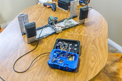
So the flash would be useless without a sensor to send a trigger signal at the appropriate time. My ballistic chronograph will act as the sensor. The chronograph is already set up to control some typical camera speedlight flashes, so I designed the high-speed flash to use a similar signal.
The flash has a 3.5mm audio cable port. The tip is connected to a pin on the controller. The pin is set to have a pullup resistor in the firmware. The base of the 3.5mm port is grounded to the controller. When the flash is activated, it waits until the pin goes low before firing. I used an active-low signal because it’s common with cameras and speedlight flashes, so it may as well be consistent.
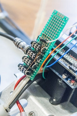
On the chronograph, I made an interface board with four 3.5mm audio ports. Each port has a tip connection to a GPIO pin, and the bases are grounded. The controller GPIO pins are held in tri-state (input) mode, then source (output low) when activated. The ports can control speedlight or this high-speed flash, a camera, and even an automated trigger on my air rifle.
Each port has a clamping diode. This protects the controller in case a device with reversed polarity (tip-ground) is plugged in. I should also add a zener clamping diode to protect the controller in case a device with more than 5V is plugged in, but for now I will just be careful. In the past I’ve used opto-isolators, but those introduce their own lag and complicate the entire system – not worth it.
Firmware
The firmware for the flash is available on Github. It’s pretty simple – an encoder selects the flash duration and trigger delay, and a long-hold executes a flash immediately (the complete user’s manual is available on Github). While the capacitors are charging, I can hold the button and the display will continue to show the voltage output from the booster. This helps for adjusting the high-voltage rail. There’s also a diagnostics test that checks how the system charges and discharges.
The pulse duration, pre- and post-flash voltages, and current draw for each flash pulse are recorded to EEPROM, and I can review the data using a serial terminal on my PC. This allows me to monitor the long-term health of the electronic components in case anything gets damaged or worn. The ATMega328P has 1kB of EEPROM, and each data entry uses 3 bytes. There is room for 340 entries, so I can probably download and clear the data monthly or yearly.
Future Updates?
Here’s a list of changes I plan for this flash. I don’t plan on making heavy modifications to this flash, given that it seems to work so well. Note that a brand-new ‘Mark 2’ is in development and I will update this post when the prototype is functional.
- (Coming in the Mark 2) -> A lower-power boost capacitor optimized for low-current supply. Unfortunately that probably means I would have to build my own, which would be more expensive than the cheap regulator I found on eBay. But it would consume less power,
especially if I can remove the relay(DONE). - (Coming in the Mark 2) -> It’s annoying having to use 8 AA batteries, I would hope to redesign for 4 AA batteries. It will probably go through a 12 V boost regulator, which would also be helpful to maintain a 12 V gate driver voltage (instead of the driver voltage varying with battery charge).
- DONE -> An audible ‘Ready’ signal would be nice. Adding a piezo buzzer would be easy, maybe I’ll update the current board with a buzzer.
- The firmware could review the EEPROM data to check if there are any changes to the current draw over time. This may alert me to potential issues without having to download and review the data myself.
- DONE ->Thanks to Lars – Add a firmware function for ‘broken-wire triggering’ of the flash. That will make this a standalone solution for high-speed photography – no separate triggering system required.
- DONE -> Thanks to Lightning Phil – Low-Inductance series resistors to dampen the current through the LED’s.
- Thanks to TheBestJohn – An alternative case for use with 18650 or 26650 batteries.
- Thanks to Volker from Germany – A single detachable Fresnel lens to focus the light
Lower-voltage capacitors would be cheaper and smaller. These 400 V caps are overkill, I would look for some 150 V caps.Given how much voltage the LED’s can handle, I’ll continue using the 400 V caps.
This work is licensed under a Creative Commons Attribution 4.0 International License.
1 thought on “Edgerton, A High-Speed LED Flash #DIY”