
The Bubblegum Chip, Now With Steroids!
The Atmel ATTINY85 is a great chip (cheap, easy to use, supported in the Arduino IDE). Unfortunately it only has 5 IO pins, which limits its usability. There are guides on using a High-Voltage Programmer (HVP) to change the Reset pin into an IO pin. However, that prevents you from programming the Flash (Program Memory) until you re-enable the Reset pin.
Thankfully the Flash can be programmed with an HVP, but the commands and protocol are different. My USBtinyISP simply cannot be modified to be an HVP. Using an Arduino as ISP (In-Service Programmer) on an ATTINY85 is fairly simple but doesn’t work if the Reset pin is disabled.
Datasheet To The Rescue!
The datasheet describes the protocol for high-voltage programming (pp. 158 – 160). Sadly, not everything about the protocol is clear and there is at least one error!
I decided to use the ArduinoISP sketch as a starting point. The sketch is included with the Arduino IDE (File -> Examples -> Arduino as ISP). Then I edited the protocol to use the HVP protocol described in the datasheet. Bingo!
Step 1 – Hardware
There are already several guides on building an HVP. I’ll leave a link here to Paul Willoughby’s page on the topic (who, in turn, credits Jeff Keyzer). He describes how to set the fuses on an ATTINY85 using an HVP. Thanks Paul!
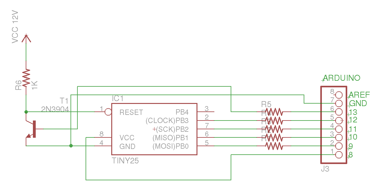
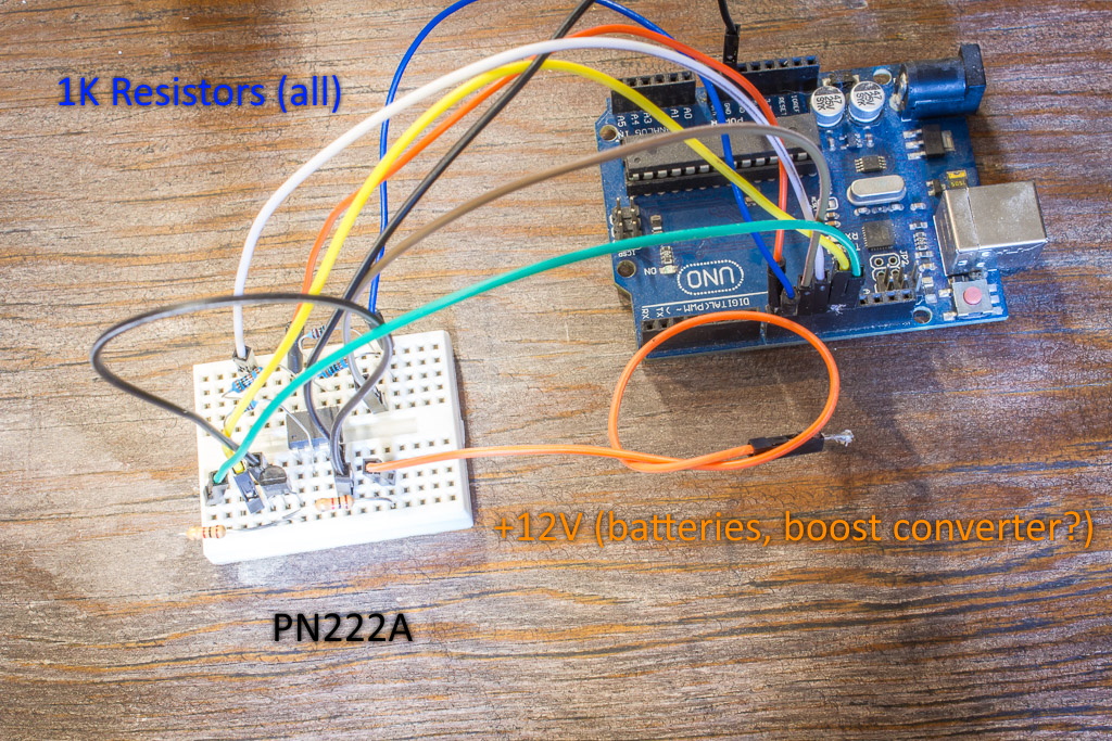
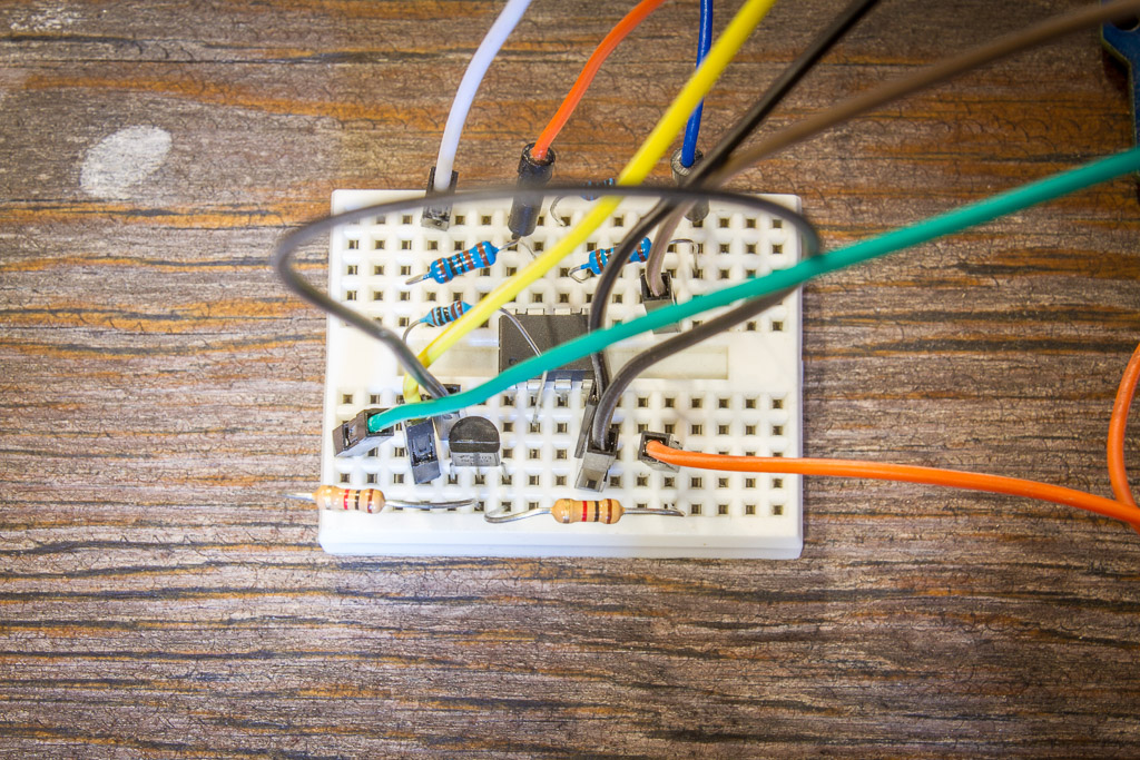
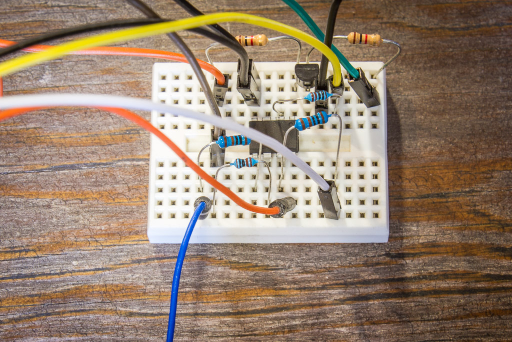
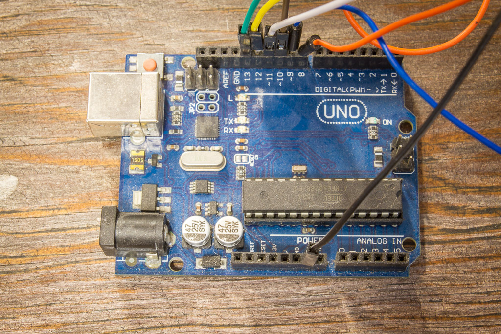
The same HVP circuit is shown on several websites. What doesn’t seem to be common is using the HVP to program the Flash. I built an HVP on perfboard using 6x 1K resistors, a PN2222A transistor, and a 5V- 12V boost converter from eBay (you can use any voltage source 11.5 – 12.5 V). Below is an example HVP setup with an Arduino Uno.
If you don’t want to wire up the HVP on a breadboard or perfboard, look at Jeff Keyzer’s HV Rescue Shield.
Step 2 – Uploading A Sketch (Programming Flash)
My modified sketch is available at https://github.com/td0g/ArduinoHVP. Simply upload it to the Arduino Uno / Nano that you are using in the HVP. Now you can upload sketches to the ATTINY85 with the HVP by selecting Tools -> Programmer -> Arduino As ISP.
Step 3 – Setting The Fuses (Disable Reset, etc.)
The fuses in the ATTINY85 affect several areas of functionality (Datasheet pp. 148,149). The most useful settings are:
- Reset pin functionality (the whole purpose of the high-voltage flash programmer!)
- Clock rate (1MHz vs 8MHz)
- EEPROM preserve during Flash programming (by default the EEPROM is erased when Flash is programmed)
Paul already described how to set the fuses in his page. I included a tool to set the fuses in my program as well. To use it, simply open a Serial console (19200 Baud) and type ‘Z’. Finally, enter your desired fuse settings. Done!
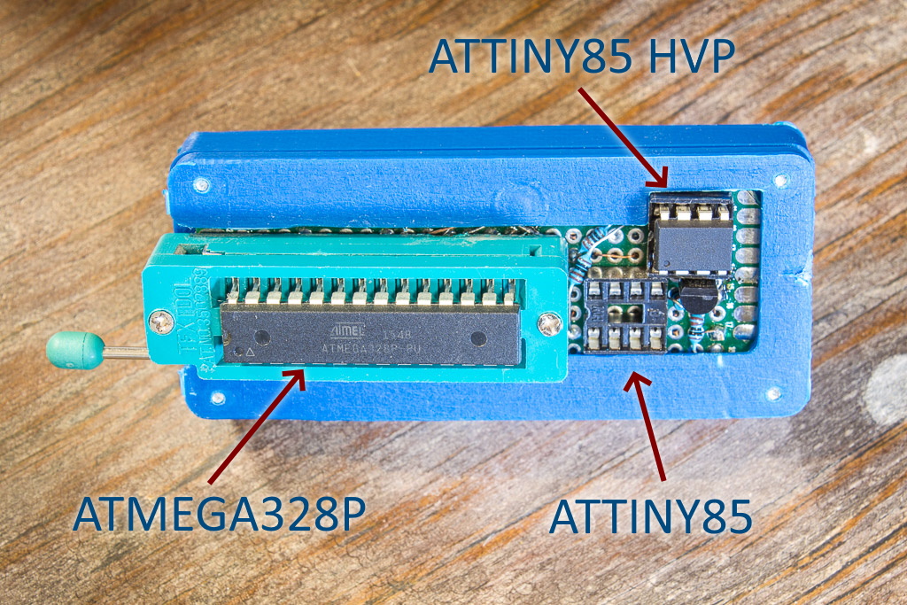
My Programmer
Here’s a few photos of my programmer. It’s a fairly useful board that straps onto an Arduino Nano.
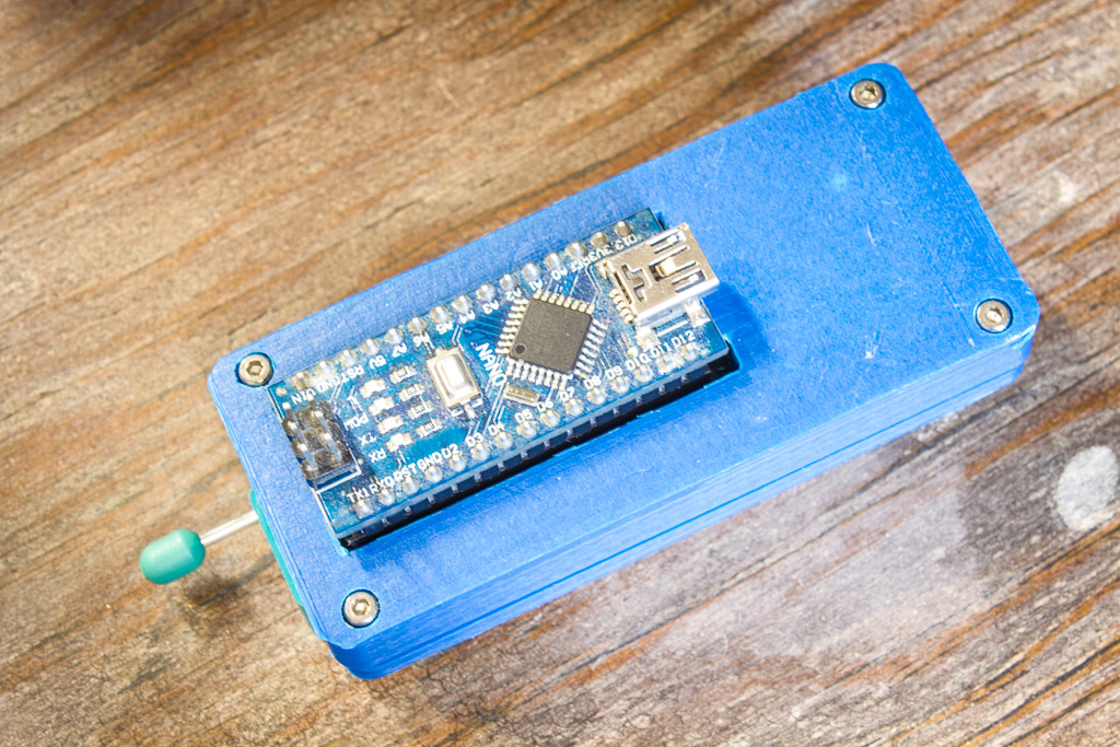
It can be used to program an ATMEGA328P and ATTINY85 (standard AND high-voltage programming). I use a few different sketches on the Nano depending on what’s needed:
- ArduinoISP – This sketch is useful for programming an ATMEGA328P or ATTINY85 without burning a bootloader. It’s also come in handy to program a stubborn ATTINY85 when my USBtinyISP fails.
- Nick Gammon’s ATMEGA toolkit – If you use ATMEGA328P microcontrollers in your projects, go get Nick’s board programming tools NOW! I use them to burn bootloaders on my microcontrollers.
- ArduinoHVP – What this whole post was about.
Thanks for reading!