
Measuring Air Flow – Made Easy
A sonic anemometer is a device that measures air velocity using sound. A speaker on one end of the device emits a ‘ping’, and a sensor waits for the ping to arrive. If the air is not moving, then the delay between ‘pinging’ and ‘receiving’ is always the same (kinda).
If the air is moving from the sensor toward the emitter, then the delay gets longer since the ping is traveling upstream. Conversely, if the air is moving from the emitter toward the sensor, then the delay gets shorter since the ping is traveling downstream.
I built this anemometer to measure airflow rates of various small fans.
Ingredients
All you need is an Arduino, an HC-SR04 ultrasonic distance sensor, a piece of 3/4″ PVC conduit, and a 3D printer. The 3D print file and firmware is available on Github.
3D print the sonic anemometer ends twice. Take the HC-SR04 and remove the sender and emitters. Put them inside the 3D printed ends and connect them back to the HC-SR04 with very light wire (22-guage or lighter). Done!
Arduino Code
I wrote a bit of Arduino code for the test. It’s accuracy is sub-microsecond (which is better than the built-in micros() function Arduino carries). Note that this is only tested on the Arduino Uno. Connect the TRIG pin to Arduino pin 2 and the ECHO pin to Arduino pin 3.
How Sensitive Is It?
I ran an experiment to see how sensitive the instrument is. Rather, my kids (6M, 4F) and I ran the test.
We grabbed an empty paint can and mounted the anemometer to the lid. Next, we drilled a small hole in the bottom of the can and filled the can with a known volume of water. We used a stopwatch to time how long it took for the water to run out and monitored the anemometer’s ping times. After each test we enlarged / added more holes to the bottom of the paint can. The test setup Sonic anemometer mounted on paint can lid Bottom side of lid Holes being added to paint can
I’m going to write a little about working with the kids. My boy was in charge of the stopwatch. It was a good job for him – the kid is good at technical tasks (like starting, stopping, resetting the stopwatch) but communication is a bit more of a challenge for him. We had to work as a team, and he needed to let us know if he wasn’t ready – or if he accidentally started the stopwatch early and we needed to wait! It all started out rough, but by the end of our testing, he was doing a bang-up job.
My girl handled the instrument, and was even able to drill some of the smaller holes by herself. I helped with the larger holes as the drill would grab the plastic paint can. She also loves being in charge, and as such she was given the job of directing the start of each test. It was great practice for her, as she would sometimes confuse us with an unusual start sequence (Three! Two! One! ………..(long delay)……Start!). What great practice for her!
Several things did not go according to plan, which is always expected. My primary goal was to give the kids a chance to do engineering testing, and hopefully we got some usable data in the process. I think we succeeded on both fronts!
Results
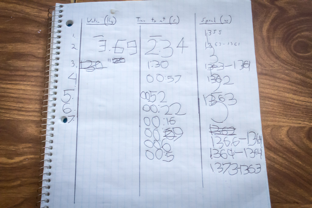
The test results were recorded by my son. The data was a little bungled and numbers were rounded liberally. I had a little difficulty transcribing them to the spreadsheet…
Here’s a more legible plot of the average flow rate vs. calculated air speed. You can see that lower airspeeds are really poorly measured, but it improves with higher airspeeds. We stopped at about 750 mL/s due to the limitations of the test design. If I come up with a better way of testing then I’ll update this post with new data!
Here’s the formula used to convert ping times to air speed: airSpeed = (pingMeasured – pingBaseline) / pingMeasured * speedOfSound
Making It Fancy!
Since I’ll probably want to use the anemometer without an Arduino hooked up, I designed and built an ATINY85-based controller. The ATTINY85 is currently using the 1MHz built-in clock, but I may use a high-voltage programmer to change it to the 8MHz built-in clock. We will see how usable the device is.
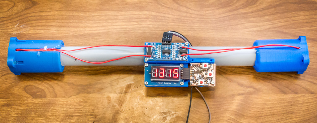
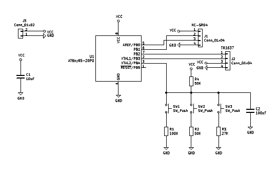
I designed the control board in KiCad and etched the board with a PCB mill. The display is a TM1637-based 7-segment display. I have the firmware and design files on Github.
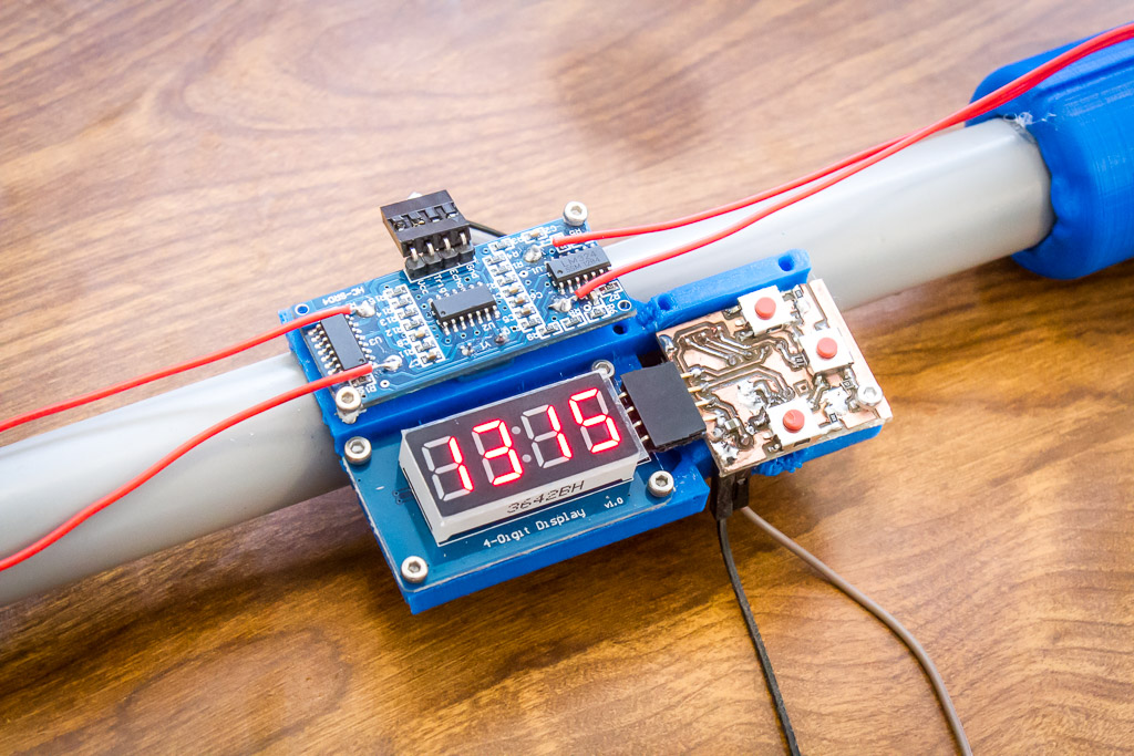
The controller has three buttons, but not much functionality. The buttons are in case I add new features in the future. For now the display simply shows the ping time in microseconds, there is a ‘zero’ button to set the zero-airspeed time, and a reset button.
Thanks for reading!
Last updated 2020-03-23
Very well thought out method of controlling and measuring air flow at essentially ambient pressure. Especially excited to see how you involved your young scientists in the project and gave them hands-on first hand experience in applied science.