You Get What You Pay For
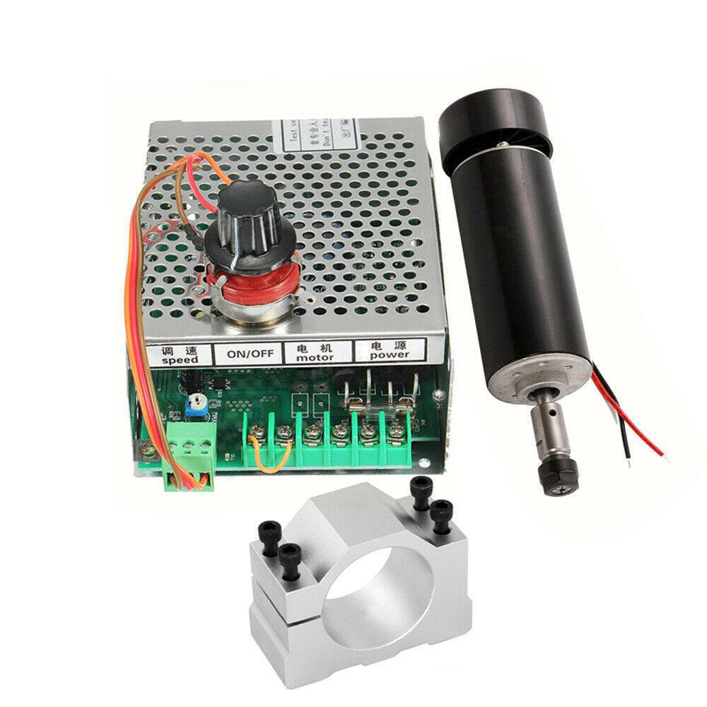
While building my CNC mill, I bought a 500W spindle with a motor controller off eBay for less than $80 CAD. The spindle and power supply needed some TLC right out of the box, but seemed to work fine.
Then the incident happened… I was adjusting the ‘MAX’ potentiometer when suddenly the motor speed dropped to 5,000 RPM and wouldn’t increase! I may have accidentally shorted the potentiometer with my screwdriver, but that shouldn’t have caused a problem. This potentiometer is basically shorted to 0 ohms at one end anyways.
No adjustments to any of the potentiometers would change the motor speed more than a few hundred RPM. I considered buying a replacement controller, but for $50 CAD I decided to have a crack at repairing this unit. I ended up writing an almost-complete schematic of the controller and determining what one of the three IC’s are.
Schematic for 500W Spindle Controller / Power Supply
The Undocumented Motor Controller
As I expected, the motor controller did not come with any documentation. Nobody seems to have a schematic online! I was browsing eBay, and noticed some controllers that look similar (identical?) and were rated for 300W. The eBay listing for my controller says it can output 0 – 100V and 6A, but now I’m suspicious. An under-rated motor controller would explain all the resetting issues it has caused in the past!
During my repair, I also spent some time trying to figure out if this controller is good to handle 500W. TLDR: The semiconductors are ok, but the capacitor might be too small.
They Removed The Model Numbers!
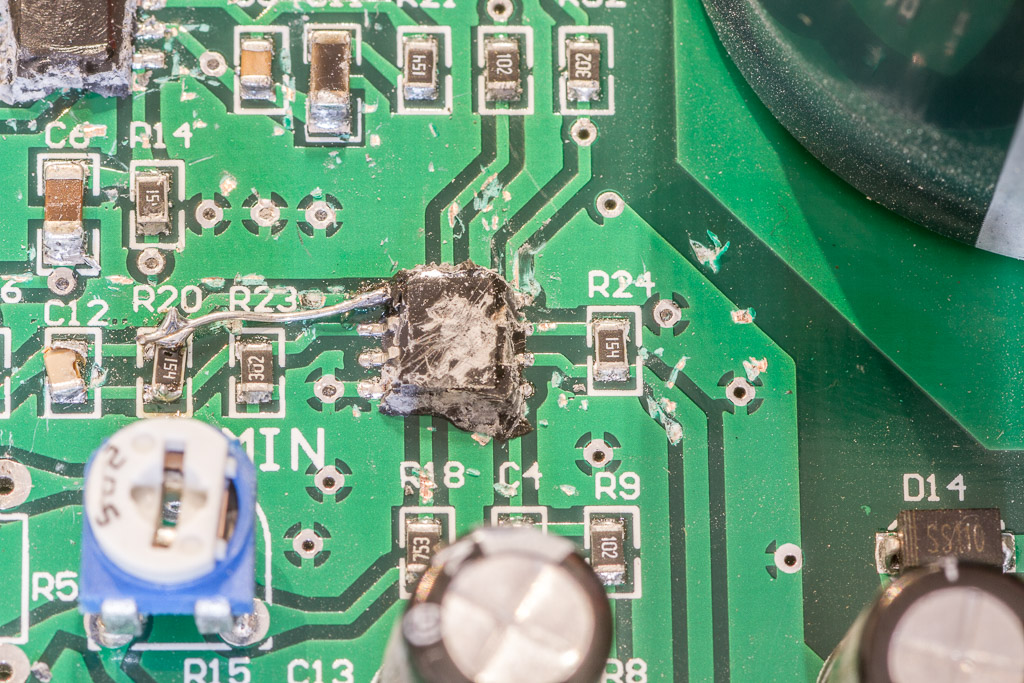
I had already cracked the case open and found a big blob of potting material on the board. It looked like the manufacturer was trying to hide the IC model numbers. A third IC wasn’t covered with the goop, but the model numbers were scratched off.
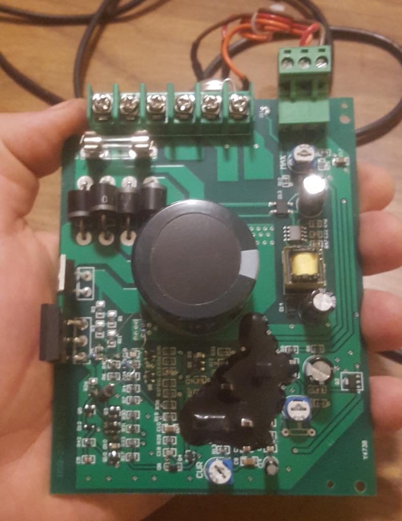
I wanted to reverse engineer the entire board in order to understand the problem. I used a torch to heat a knife and picked away at the blob for about an hour. In the process, I uncovered most of the traces, accidentally knocked off a resistor, capacitor, damaged a trace, and ripped off an IC pin (which lead to an interesting discovery – keep reading). I replaced the resistor and repaired the trace, and the controller then worked just like before the blob was cut off.
Unfortunately the IC model numbers were still indiscernable! I had to do some sleuthing to figure out what they were. I started by creating a circuit diagram.
The Circuit
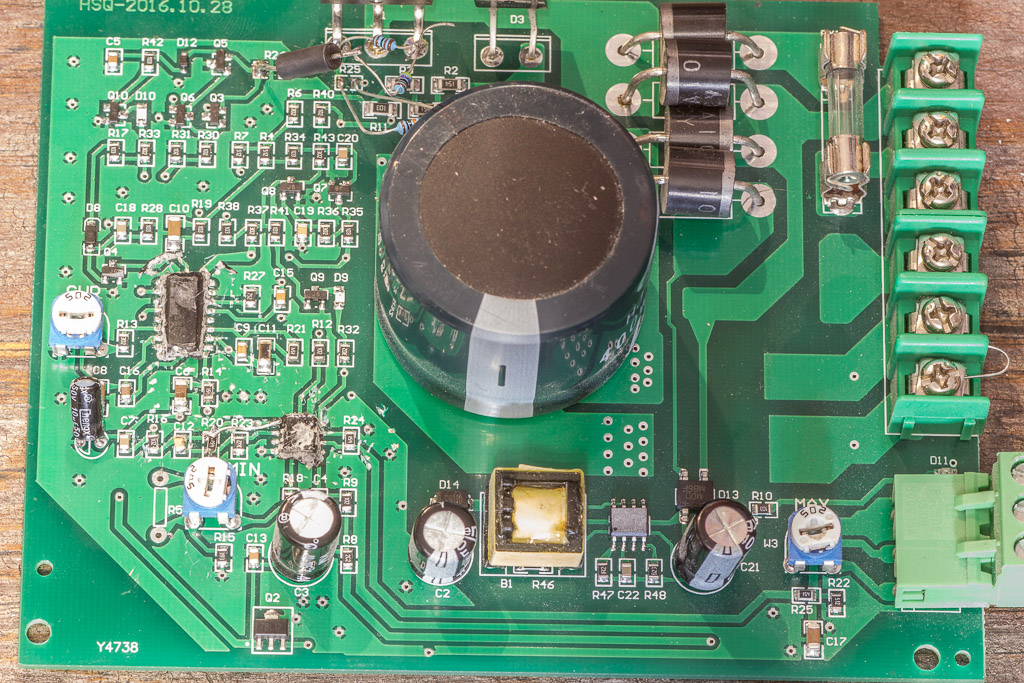
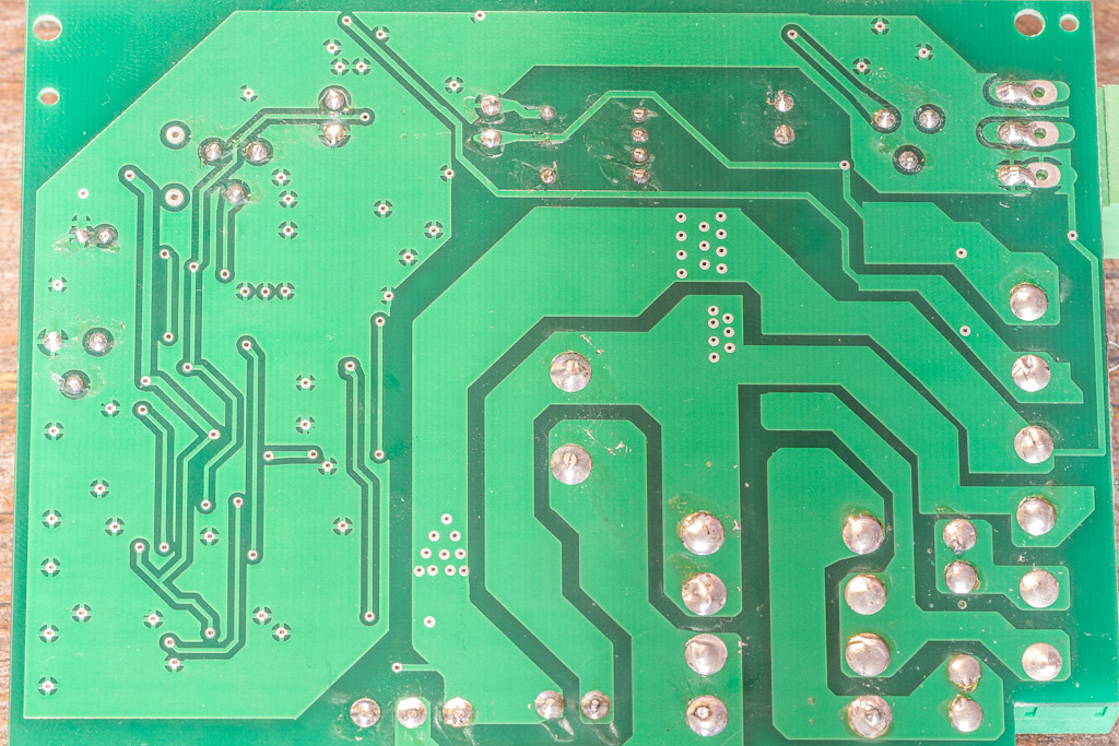
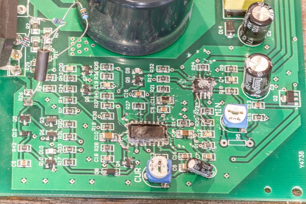
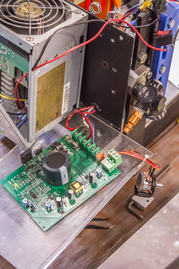
Here are some photos of the board. The rectifier and switching elements are on the central and top right section, the 12V flyback converter is near the bottom, and the PWM control circuitry is on the left.

The main rectifier diodes are in a row next to the AC input fuse. The 330uF capacitor in the middle smooths out the rectified power. The isolation transformer is… absent. So the output power is NOT floating!
The ground poor for is actually tied to the PWM MOSFET’s drain. The control voltage is provided by a second rectifier and a flyback transformer (shown below). The model number of the flyback controller is scratched off, but the output is connected to a 78L12 linear regulator to provide +12V.
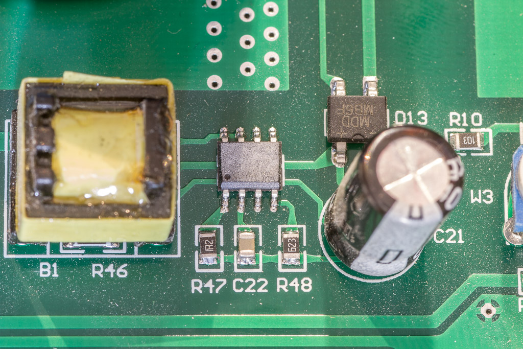
There’s a SOIC-8 chip connected to the MIN, MAX, and SPEED potentiometers. I’m not sure what it is, but best guess is an op-amp. I damaged the trace coming from the number one pin and had to repair it. The spindle did NOT work until I made the repair.
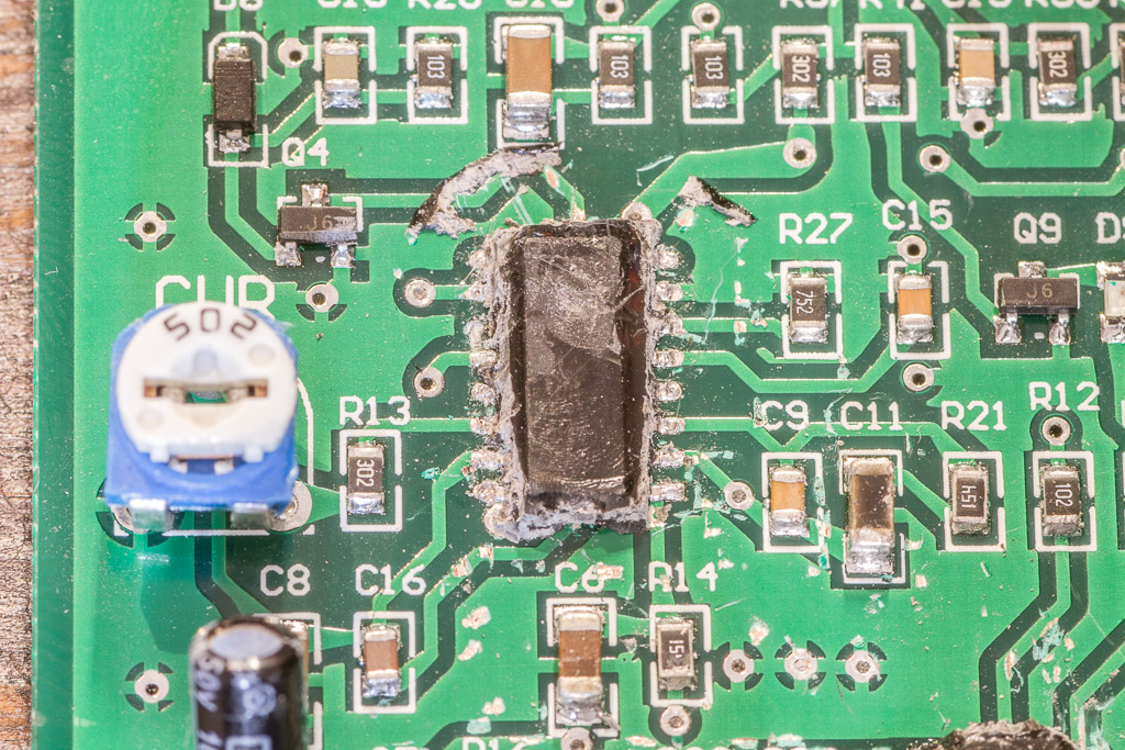
Using the circuit diagram, I searched Digikey for buck controllers in a SOIC-16 package and found three potential candidates for the larger IC: TI TL494, TI TL494, or Diodes Incorporated AZ7500B. Interesting how these parts from two different manufacturers have the exact same pinout…
Note how I destroyed the #11 pin (the package is photographed upside-down). In the datasheets, this pin is intended to be connected to pin #8 so that the internal BJT’s are in parellel. It would seem that I may have knocked off a redundant pin. Lucky!
I also had a look at the MOSFET and flyback diode to see if they could handle a 5A, 100V inductive load.
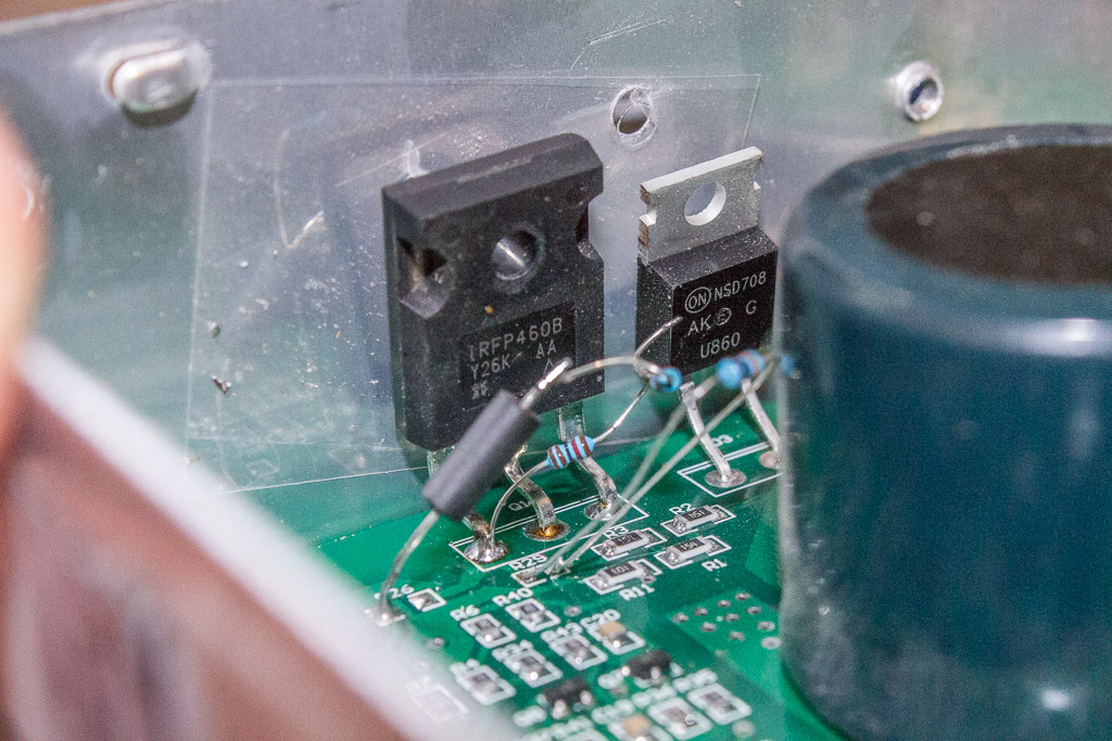
The switching element is a Vishay IRFP460B N-Channel FET. Its rated Vds is 500V and its Id is 13A. At first glance, these look good. I searched for an NSD708 diode, and instead got a listing for a Motorola MUR820/840/860 Diode. It’s in a TO-220 package, polarity is correct, and the bottom of the diode says ‘U860’ so I think this may be our diode. Peak repetitive forward current is 16A and peak repetitive reverse voltage is 600V for the MUR860. This is an ultrafast schottky diode, so I think it should be good for the job.
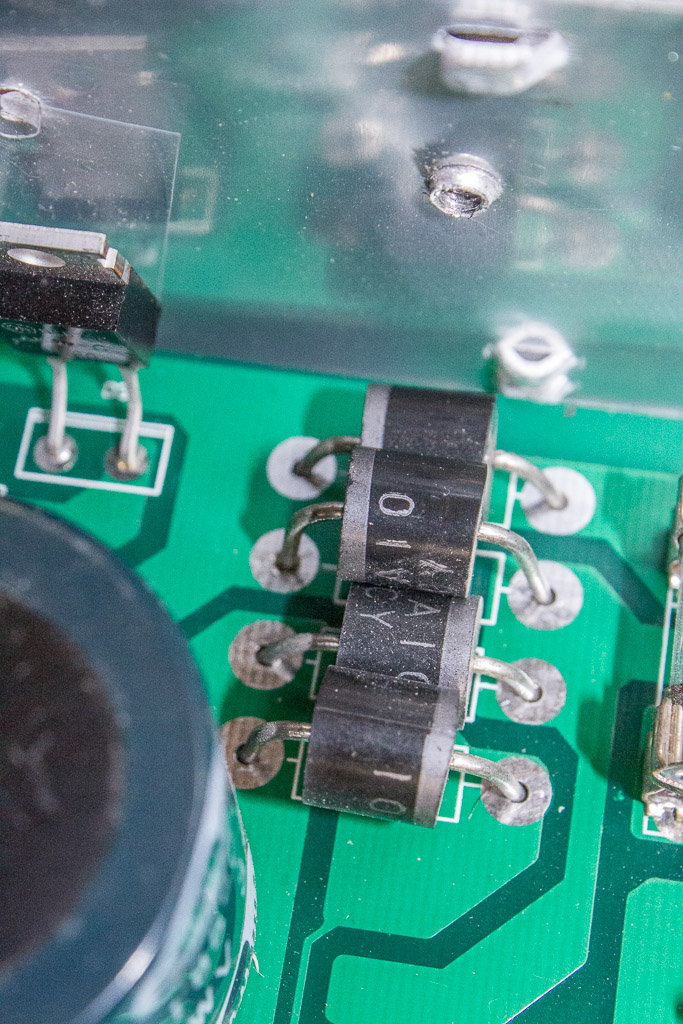
The rectifier diodes look pretty bulky. I should check the forward voltage when it is on…
The Repair
I admit failure in that I never discovered what had changed or become damaged on the board. However, I did return the board to its original function by adding only one resistor! R8 is a 2K resistor, and I simply added a second 2K resistor in parallel. This increased the voltage to the SPEED potentiometer!
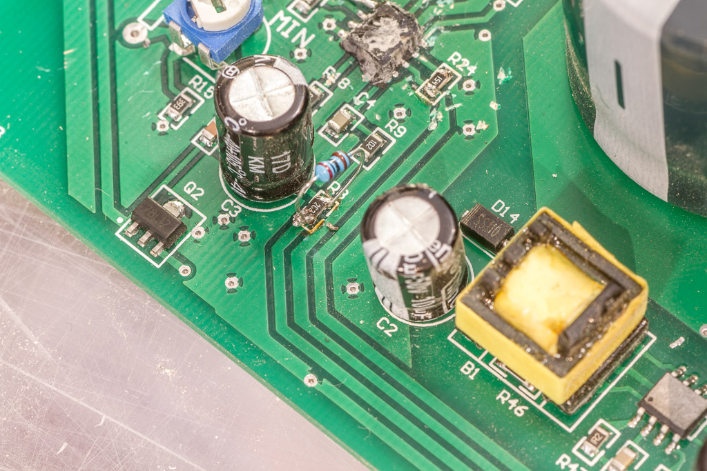
You can see the repair in the schematic. My guess is that a voltage reference or some other semiconductor became damaged when I shorted the potentiometer. Maybe it was caused by a quick voltage fluctuation? If you have an educated guess, please leave a comment!
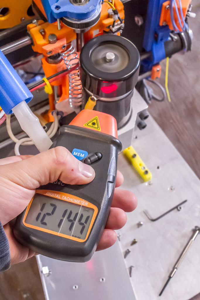
Next, I had to set the MIN and MAX potentiometers. I did this using a laser tachometer to set it to 3,500 – 12,000 RPM.
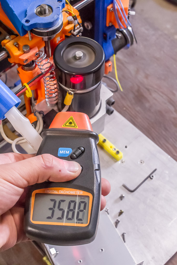
Time to put everything back together!
Thanks for reading!
Last Updated 2019-11-30
My motor controller isn’t working now. Without a spindle all is ok. Output voltage is down to zero and red diod d9 is bright when I use the spindle. I think to change IRF640b.