I recently added a couple home-build devices to my home lab. The first is a well-designed PCB jig engineered by an electronics forensic expert. The second is a very cheap lab power supply using a Chinese step-down converter and an old battery charger.
The Jig
It seems I never have enough hands, especially while testing and troubleshooting a fresh PCB. As frustration was mounting recently, Thingiverse member Giufini seemingly heard my prayers – and shared his design for a PCB probe jig!
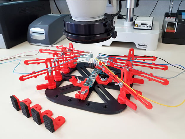
At first glance, it looks somewhat hap-hazard. I built one, and must say that it is very well designed! The layout of the board is perfect for the PCB’s I work with. The towers and arms are easy to adjust and have a well-tuned flexibility to them. Finally, the acupuncture needles were simply genius! This design was even reviewed (and quite well received) on Superhouse.
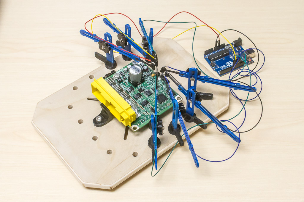
My build uses a piece of plywood for the base. That’s simply because I have a CNC mill to do the work, and it would be cheaper and faster than 3D printing the base.
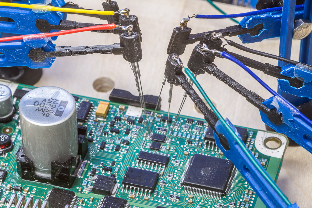
Giufini suggests printing the arm ends with a smaller nozzle, but I decided to just use the 0.4 mm nozzle and use a 1.0mm drill bit to clear the path for the needle. The acupuncture needles aren’t easy to solder. I heard that some people were using ferules to attach the wires, but I decided to just use solder. Start by wrapping the bare wire around the needles several times. It seems to work fine.
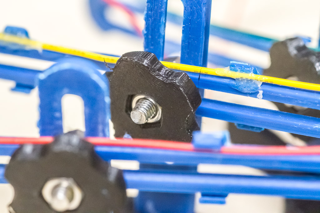
Instead of the wing nuts suggested by giufini, I printed a set of thumb nuts. They’re nice to use as you can just roll your finger over them to tighten. Adjusting the arms is really a pleasure – nice work giufini!
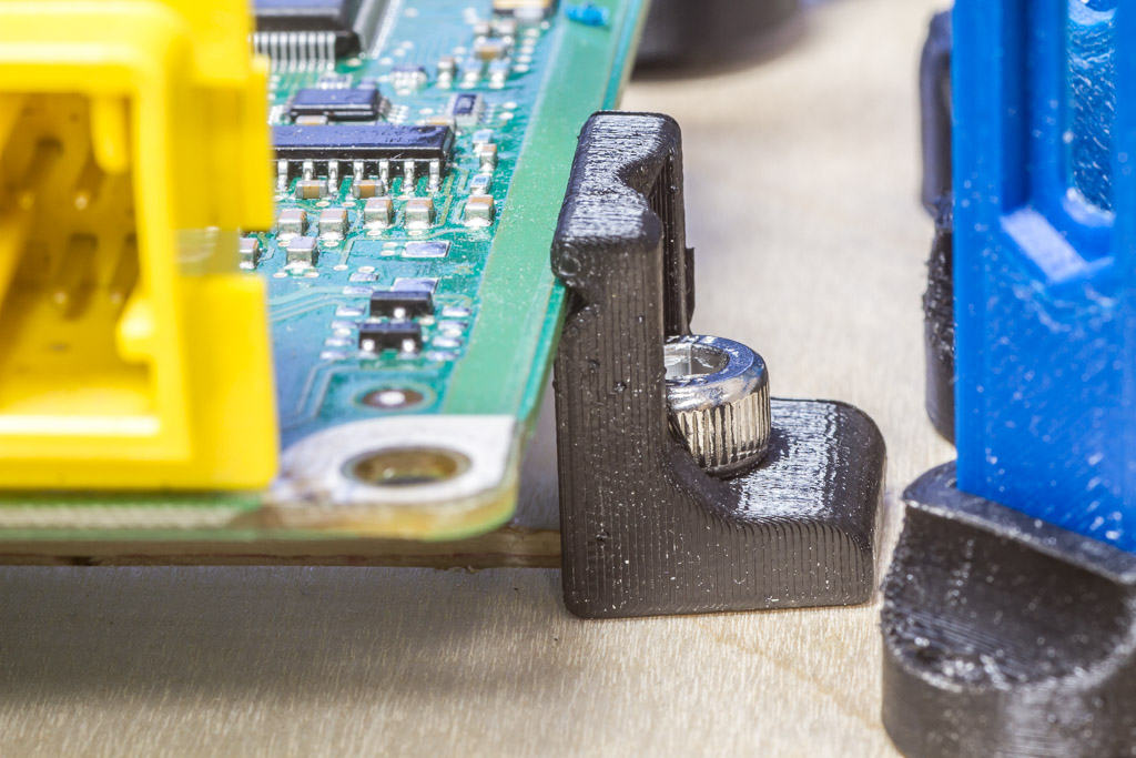
The first board I probed was just slightly large for the jig. So I designed a low-profile mount. It requires an allen key to use, which is unfortunate as giufini’s original mounts all used wing nuts and were easy to use. This does expand the maximum PCB size and may be handy for some users.
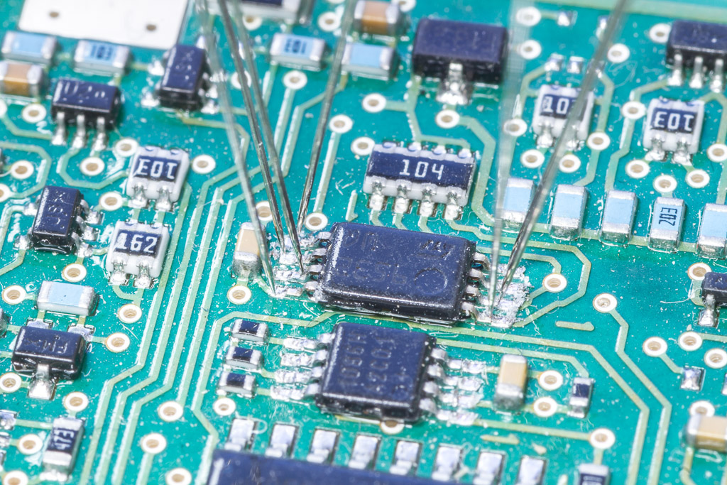
That’s an MSOP-package EEPROM that I successfully imaged on the first try! Thanks giufini!
The Power Supply
TL;DR: Old cordless drill chargers might have a decent transformer, which can be coupled to a cheap step-down converter to make a cheap lab power supply!
My lab power supply left quite a bit to be desired – it was just an ATX PSU with fuses and banana jacks. Oh the fuses I went through… So recently I ordered a DP50V5A step-down converter from eBay ($35 CAD). It’s a cute little converter that’s intended to be a constant-voltage and constant-current power supply, but it doesn’t actually come with a supply. That’s up to the end user to configure.
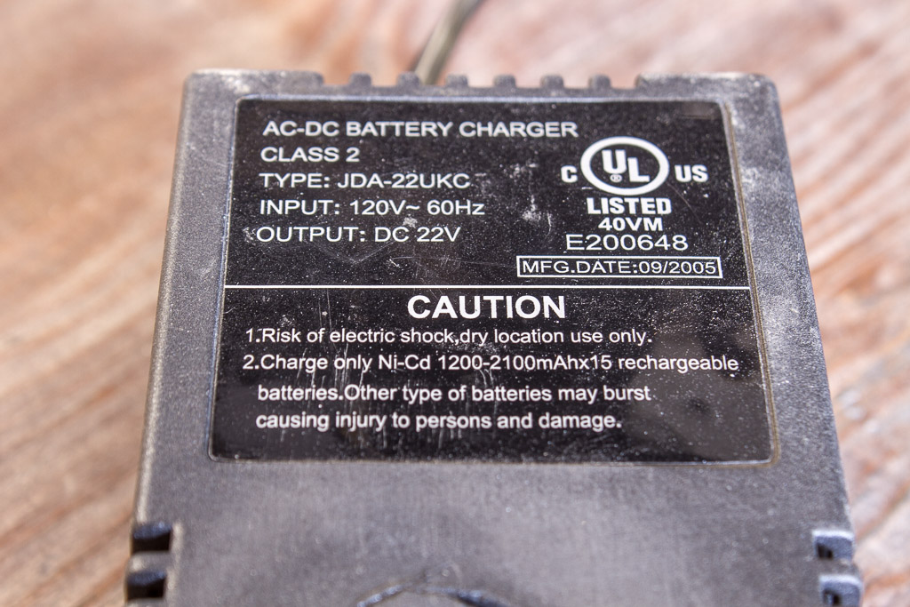
While waiting for the unit to arrive, I stumbled upon an old cordless drill and charger. The charger weighed a TON! So there must be a decent transformer inside there. Checked the specs – 22V would be a decent power supply for now. I later checked it with an oscilloscope and found it was 28V max!
I added a pair of 680uF capacitors (from an old ATX PSU) and a rectifier. Under no-load, the voltage is fairly steady at 28V.
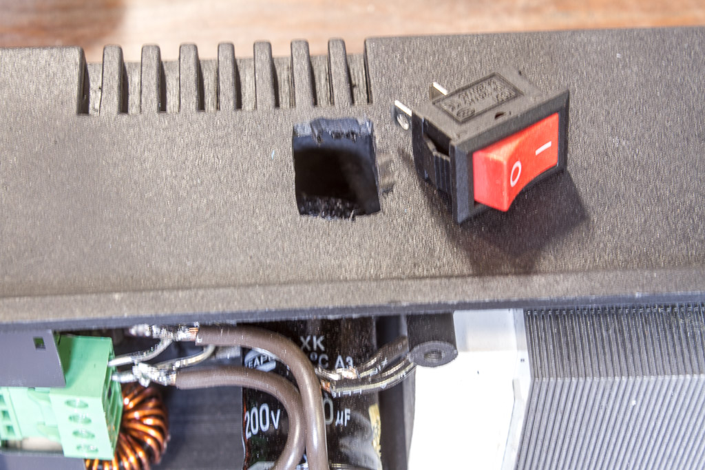
It was all surprisingly tight once the power switch, banana jacks, and fuse were installed. I put the fuse in series with the power switch to limit the total input current.
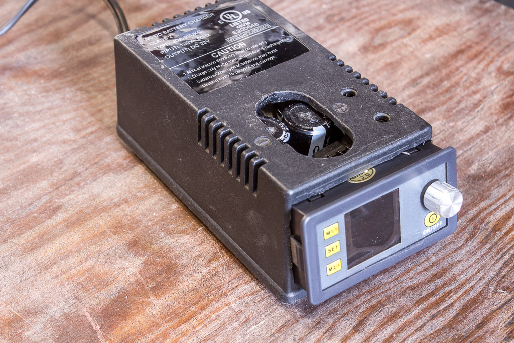
There was a massive hole in the top of the case. I had some extra plastic left over from all the internal trimming. Cut out a piece of plastic to fill the hole, then used a soldering iron to plastic-weld it in place. Some sanding, and it doesn’t look bad…
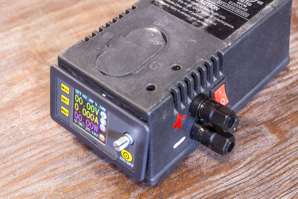
So there could be a nice little bezel to better fit the step-down converter to the case, but I think it looks decent for the price! It’s compact and I really like the step-down converter. It will provide several amps at 5 volts, and about 2 amps at 20 volts. For about $40 total, I’m happy.
Thanks for reading!
Last updated 2020-02-19